Infiniti G35 (V35) Sedan. Manual - part 714
TRANSVERSE LINK
FSU-13
< ON-VEHICLE REPAIR >
[2WD]
C
D
F
G
H
I
J
K
L
M
A
B
FSU
N
O
P
TRANSVERSE LINK
Exploded View
INFOID:0000000000957771
Removal and Installation
INFOID:0000000000957772
REMOVAL
1.
Remove tires with power tool.
2.
Remove under cover with power tool.
3.
Remove shock absorber. Refer to
FSU-9, "Removal and Installation"
.
4.
Remove steering outer socket from steering knuckle. Refer to
ST-27, "2WD : Removal and Installation"
.
5.
Remove transverse link from steering knuckle. Refer to
ST-27, "2WD : Removal and Installation"
6.
Set suitable jack under transverse link.
7.
Remove mounting bolts and nuts, and then remove transverse link.
INSTALLATION
Note the following, and install in the reverse order of removal.
CAUTION:
Never tap on the ball joint cap of the stabilizer connecting rod with a hammer or a similar item when
inserting the stabilizer connecting rod into the transverse link.
• Perform final tightening of bolts and nuts at the front suspension member installation and shock absorber
lower side (rubber bushing), under unladen conditions with tires on level ground.
Inspection
INFOID:0000000000957773
INSPECTION AFTER REMOVAL
Visual Inspection
Check the following:
• Transverse link and bushing for deformation, cracks or damage. Replace it if a malfunction is detected.
• Ball joint boot for cracks or other damage, and also for grease leakage. Replace it if a malfunction is
detected.
Ball Joint Inspection
Manually move ball stud to confirm it moves smoothly with no binding.
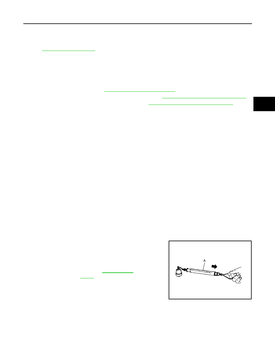
Swing Torque Inspection
NOTE:
Before measurement, move ball stud at least ten times by hand to check for smooth movement.
• Hook a spring balance (A) at cotter pin mounting hole. Confirm
spring balance measurement value is within specifications when
ball stud begins moving.
- If it is outside the specified range, replace transverse link assem-
bly.
Rotating Torque Inspection
Standard
Swing toque
: Refer to
JPEIA0005ZZ