Infiniti G35 (V35) Sedan. Manual - part 620
ENGINE ASSEMBLY
EM-79
< REMOVAL AND INSTALLATION >
C
D
E
F
G
H
I
J
K
L
M
A
EM
N
P
O
1.
Remove A/T fluid cooler hoses (A/T models) and power steering oil pump oil cooler hoses.
• Install plug to avoid leakage of A/T fluid and power steering fluid.
2.
Disconnect heated oxygen sensor 2 harness.
3.
Remove three way catalyst and exhaust front tube. Refer to
.
4.
Disconnect steering lower joint at power steering gear assembly side, and release steering lower shaft.
Refer to
.
5.
Remove rear propeller shaft. Refer to
(A/T models).
6.
Disengage shift lever and remove clutch tube (M/T models). Refer to
TM-26, "Removal and Installation"
7.
Disengage A/T control rod at control device assembly side. Then, temporarily secure it on the transmis-
sion assembly, so that it does not sag (A/T models). Refer to
.
8.
Remove rear plate cover from oil pan (upper). Then remove bolts fixing drive plate to torque converter (A/
T models). Refer to
EM-96, "2WD : Disassembly and Assembly"
9.
Remove transmission joint bolts which pierce at oil pan (upper) lower rear side. Refer to
.
10. Remove front stabilizer connecting rod from transverse link. Refer to
.
11. Remove lower ends of left and right steering knuckle from transverse link. Refer to
.
12. Separate steering outer sockets from steering knuckle. Refer to
13. Remove transverse links mounting bolts at suspension member side. Refer to
Removal Work
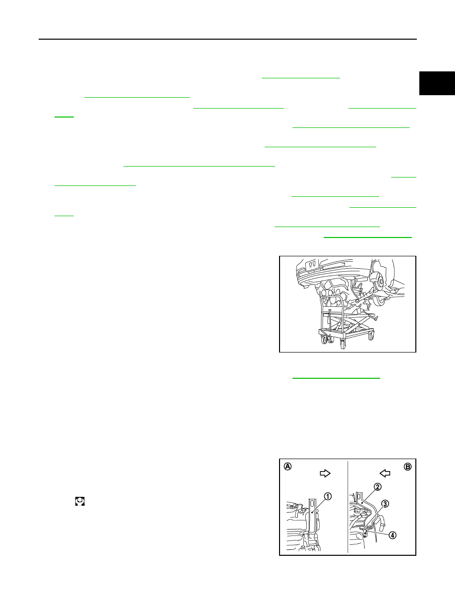
1.
Use a manual lift table caddy (commercial service tool) or equiv-
alently rigid tool such as a transmission jack. Securely support
bottom of suspension member and the transmission assembly.
CAUTION:
Put a piece of wood or something similar as the supporting
surface, secure a completely stable condition.
2.
Remove rear engine mounting member bolts.
3.
Remove front suspension member mounting bolts and nuts. Refer to
4.
Carefully lower jack, or raise lift to remove the engine, the transmission assembly and front suspension
member. When performing work, observe the following caution:
CAUTION:
• Confirm there is no interference with the vehicle.
• Make sure that all connection points have been disconnected.
• Keep in mind the center of vehicle gravity changes. If necessary, use jack(s) to support the vehi-
cle at rear jacking point(s) to prevent it from falling it off the lift.
Separation Work
1.
Install engine slingers into front of cylinder head (right bank) and
rear of cylinder head (left bank).
PBIC0804E
Slinger bolts:
: 28.0 N·m (2.9 kg-m, 21 ft-lb)
1
: Engine front slinger
2
: Engine rear upper slinger
3
: Spacer
4
: Engine rear lower slinger
A
: Right bank
JPBIA0157ZZ