Infiniti G35 (V35) Sedan. Manual - part 603


  Index      Infiniti     Infiniti G35 (V35) Sedan - service repair manual 2007 year


Search            


Content   ..  601  602  603  604   ..


Infiniti G35 (V35) Sedan. Manual - part 603


PREPARATION

EM-11

< PREPARATION >

C

D

E

F

G

H

I

J

K

L

M

A

EM

N

P

O

(

)

Valve seat cutter set

Finishing valve seat dimensions

(

)

Piston ring expander

Removing and installing piston ring

(

)

Valve guide drift

Removing and installing valve guide
Intake and Exhaust:
a: 9.5 mm (0.374 in) dia.
b: 5.5 mm (0.217 in) dia.

(

)

Valve guide reamer

A: Reaming valve guide inner hole
B: Reaming hole for oversize valve guide
Intake and Exhaust:
c: 6.0 mm (0.236 in) dia.
d: 10.2 mm (0.402 in) dia.
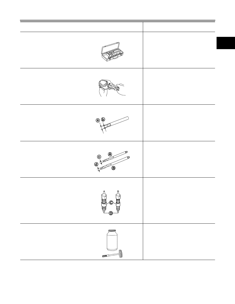
(J-43897-18)
(J-43897-12)
Oxygen sensor thread cleaner

Reconditioning the exhaust system threads 
before installing a new air fuel ratio sensor and 
heated oxygen sensor (Use with anti-seize lu-
bricant shown below.)
A: J-43897-18 [18 mm (0.71 in) dia.] for zir-
conia heated oxygen sensor and air fuel 
ratio sensor
B: J-43897-12 [12 mm (0.47 in) dia.] for tita-
nia heated oxygen sensor
C: Mating surface shave cylinder
D: Flutes

(

)

Anti-seize lubricant (Permatex 133AR 
or equivalent meeting MIL specifica-
tion MIL-A-907)

Lubricating oxygen sensor thread cleaning 
tool when reconditioning exhaust system 
threads

(Kent-Moore No.)
Tool name

Description

NT048

NT030

JPBIA0400ZZ

JPBIA0401ZZ

JPBIA0238ZZ

AEM489

EM-12

< ON-VEHICLE MAINTENANCE >

DRIVE BELTS

ON-VEHICLE MAINTENANCE

DRIVE BELTS

Exploded View

INFOID:0000000000956223

Checking

INFOID:0000000000956224

WARNING:

Be sure to perform the this step when engine is stopped.
• Make sure that the indicator (C) (notch on fixed side) of drive belt auto-tensioner is within the possible use

range (A).
NOTE:
• Check the drive belt auto-tensioner indication when the engine is cold.
• When new drive belt is installed, the indicator (notch on fixed side) should be within the range (B) in the fig-

ure.

• Visually check entire drive belt for wear, damage or cracks.
• If the indicator (notch on fixed side) is out of the possible use range or belt is damaged, replace drive belt.

Tension Adjustment

INFOID:0000000000956225

Refer to 

EM-141, "Drive Belt"

.

Removal and Installation

INFOID:0000000000956226

REMOVAL

1.

Remove radiator reservoir tank. Refer to radiator.

2.

Remove engine undercover with power tool.

3.

Remove radiator cooling fan assembly. Refer to

JPBIA0002ZZ

1.

Power steering oil pump

2.

Alternator

3.

Drive belt auto-tensioner

4.

Crankshaft pulley

5.

A/C compressor

6.

Idler pulley

7.

Drive belt

8.

Idler pulley

A.

Possible use range

B.

Range when new drive belt is installed

C.

Indicator

D.

View D

DRIVE BELTS

EM-13

< ON-VEHICLE MAINTENANCE >

C

D

E

F

G

H

I

J

K

L

M

A

EM

N

P

O

4.

While securely holding the square hole (A) in pulley center of
auto tensioner (1) with a spinner handle, move spinner handle in
the direction of arrow (loosening direction of drive belt). 

CAUTION:

Avoid placing hand in a location where pinching may occur
if the holding tool accidentally comes off.

5.

Under the above condition, insert a metallic bar of approximately
6mm (0.24 in) in diameter [hexagonal wrench (C) shown as
example in the figure] through the holding boss (B) to lock auto-
tensioner pulley arm.

6.

Remove drive belt.

INSTALLATION

Note the following, and install in the reverse order of removal.

CAUTION:

• Make sure drive belt is securely installed around all pulleys.
• Make sure drive belt is correctly engaged with the pulley groove.
• Check for engine oil and engine coolant are not adhered drive belt and pulley groove.

Inspection

INFOID:0000000000956227

INSPECTION AFTER INSTALLATION

• Turn crankshaft pulley clockwise several times to equalize tension between each pulley, and then confirm

tension of drive belt at indicator (notch on fixed side) is within the possible use range. Refer to

: Loosening direction of drive belt

JPBIA0003ZZ

EM-14

< ON-VEHICLE MAINTENANCE >

AIR CLEANER FILTER

AIR CLEANER FILTER

Removal and Installation

INFOID:0000000000956228

REMOVAL

1.

Unhook clips (1) and remove holder (3) from air cleaner case
(2).

2.

Remove air cleaner filter (1) from air cleaner case (2).

INSTALLATION

Note the following, and install in the reverse order of removal.
• Install the air cleaner filter by aligning the seal with the notch of air cleaner case.

KBIA3584J

3

:  Holder

4

:  Clip

JPBIA0005ZZ


Content   ..  601  602  603  604   ..