Infiniti G35 (V35) Sedan. Manual - part 451
DLN-238
< ON-VEHICLE REPAIR >
[REAR FINAL DRIVE: R200V]
SIDE OIL SEAL
SIDE OIL SEAL
M/T
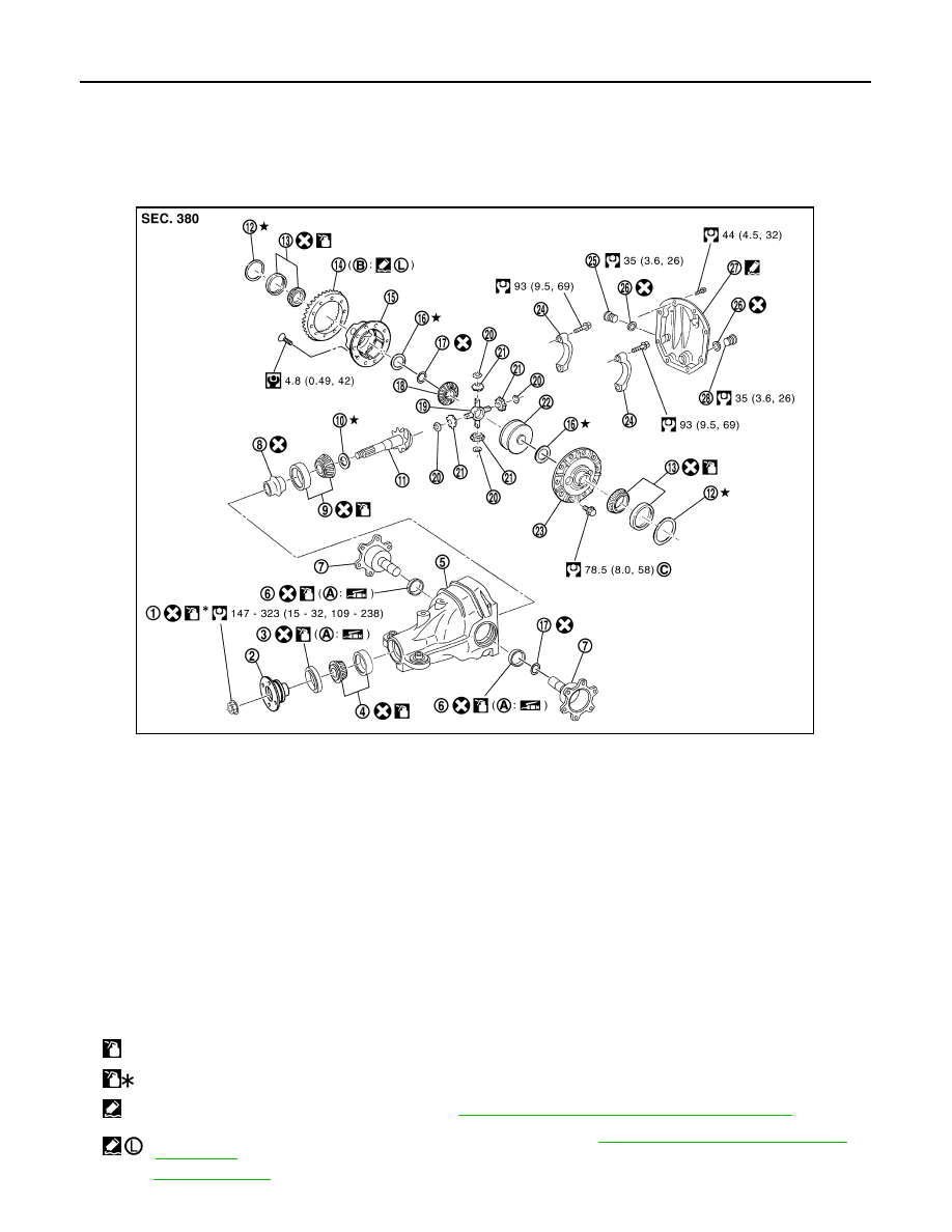
M/T : Exploded View
INFOID:0000000000957434
1.
Drive pinion lock nut
2.
Companion flange
3.
Front oil seal
4.
Pinion front bearing
5.
Gear carrier
6.
Side oil seal
7.
Side flange
8.
Collapsible spacer
9.
Pinion rear bearing
10. Pinion height adjusting washer
11.
Drive pinion
12. Side bearing adjusting washer
13. Side bearing
14. Drive gear
15. Differential case B
16. Side gear thrust washer
17. Circular clip
18. Side gear
19. Pinion mate shaft
20. Pinion mate thrust washer
21. Pinion mate gear
22. Viscous coupling
23. Differential case A
24. Bearing cap
25. Filler plug
26. Gasket
27. Rear cover
28. Drain plug
A: Oil seal lip
B: Screw hole
C: After tightening the bolts to the specified torque, tighten the bolts additionally by turning the bolts 31 to 36 degrees.
:
Apply gear oil.
:
Apply anti-corrosion oil.
:
Apply Genuine Silicone RTV or equivalent. Refer to
GI-15, "Recommended Chemical Products and Sealants"
:
Apply Genuine High Strength Thread Locking Sealant or equivalent. Refer to
GI-15, "Recommended Chemical Products
Refer to
for symbols not described on the above.
JSDIA0037GB