Infiniti G35 (V35) Sedan. Manual - part 405
DLN-54
< ON-VEHICLE REPAIR >
[TRANSFER: ETX13B]
REAR OIL SEAL
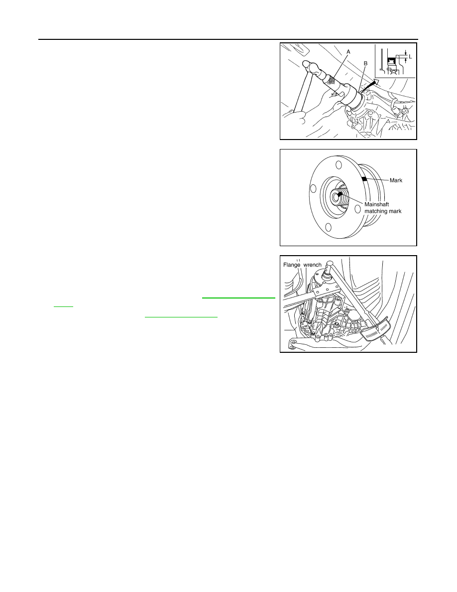
1.
Apply ATF to rear oil seal, install it with drifts.
CAUTION:
• Never reuse rear oil seal.
• When installing, never incline rear oil seal.
2.
Align the matching mark of mainshaft with the mark of compan-
ion flange, then install the companion flange.
3.
Using a flange wrench, install the self-lock nut of companion
flange and tighten to the specified torque.
CAUTION:
Never reuse self-lock nut.
4.
Install the rear propeller shaft. Refer to
.
5.
Check fluid level. Refer to
A: Drift [ST30720000 (J-25405)]
B: Drift [KV40104830 (
—
)]
Dimension “L”
: 6.7 – 7.3 mm (0.264 – 0.287 in)
JSDIA0167ZZ
SDIA2378E
PDIA0245E