Infiniti G35 (V35) Sedan. Manual - part 301
CHG
DIAGNOSIS AND REPAIR WORKFLOW
CHG-3
< BASIC INSPECTION >
C
D
E
F
G
H
I
J
K
L
B
A
O
P
N
BASIC INSPECTION
DIAGNOSIS AND REPAIR WORKFLOW
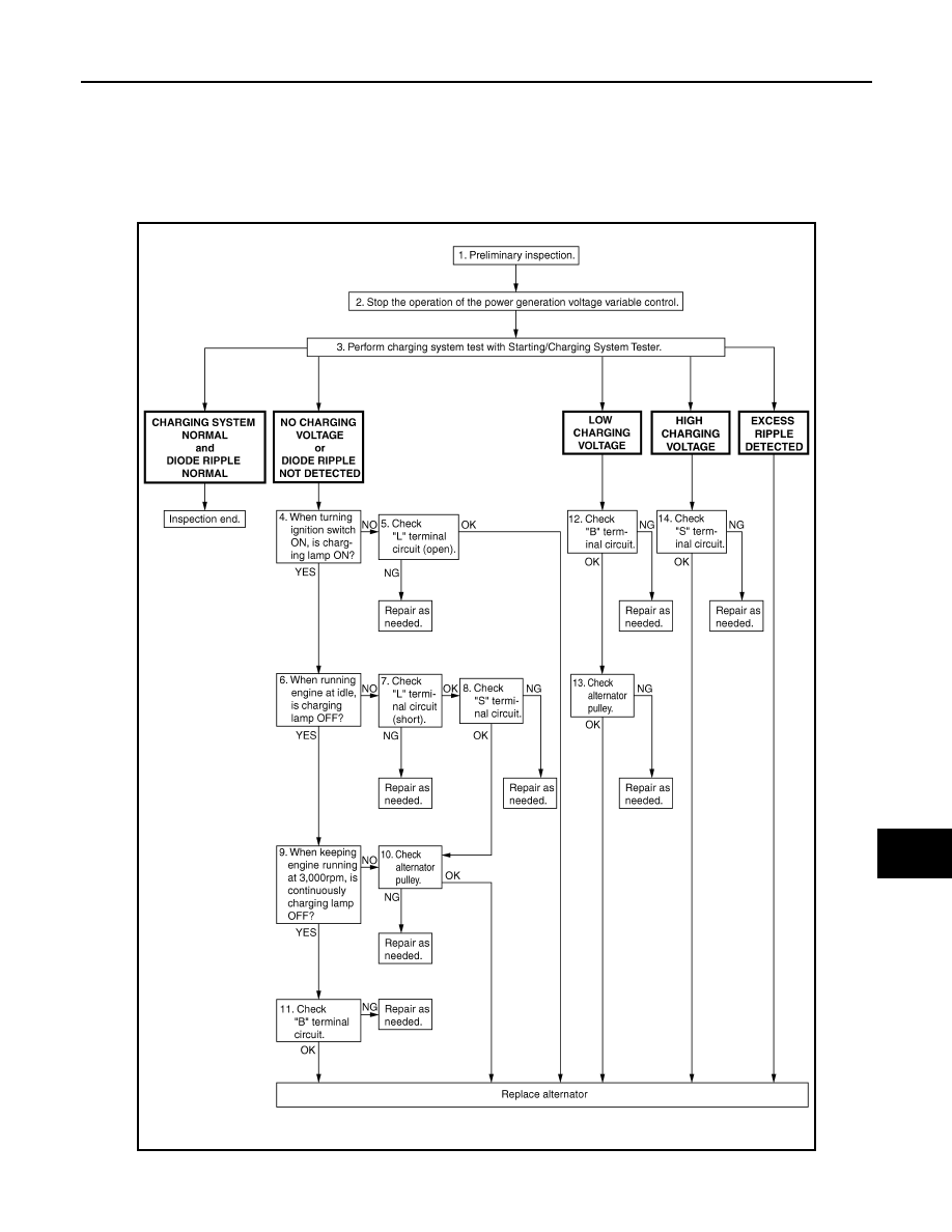
Work Flow
INFOID:0000000000964263
OVEROALL SEQUENCE
DETAILED FLOW
JSMIA0009GB