Content .. 1492 1493 1494 1495 ..
Infiniti G35 (V35) Sedan. Manual - part 1494
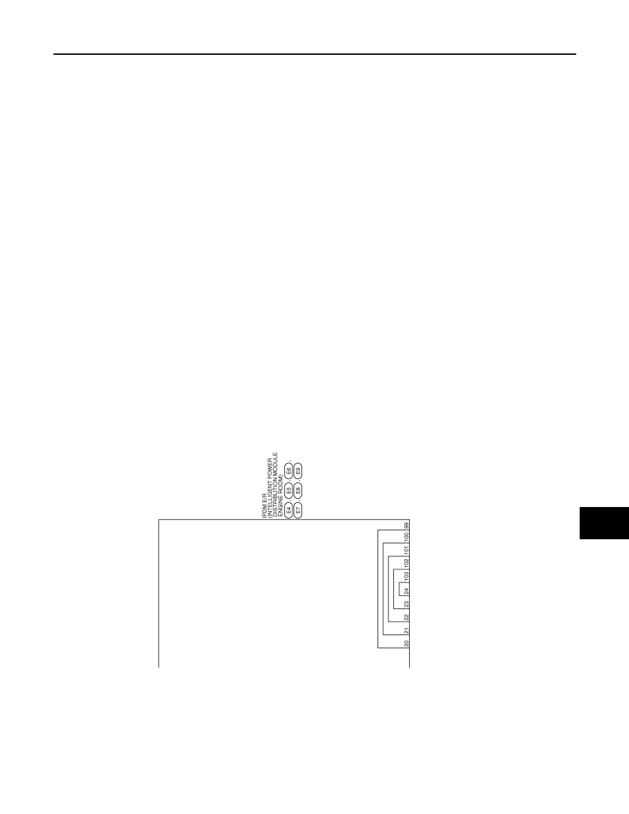
IPDM E/R (INTELLIGENT POWER DISTRIBUTION MODULE ENGINE ROOM)
WW-69
< ECU DIAGNOSIS >
C
D
E
F
G
H
I
J
K
M
A
B
WW
N
O
P
JCMWA0019GB
|
|
|
Content .. 1492 1493 1494 1495 ..
IPDM E/R (INTELLIGENT POWER DISTRIBUTION MODULE ENGINE ROOM) WW-69 < ECU DIAGNOSIS > C D E F G H I J K M A B WW N O P JCMWA0019GB |