Content .. 1491 1492 1493 1494 ..
Infiniti G35 (V35) Sedan. Manual - part 1493
IPDM E/R (INTELLIGENT POWER DISTRIBUTION MODULE ENGINE ROOM)
WW-65
< ECU DIAGNOSIS >
C
D
E
F
G
H
I
J
K
M
A
B
WW
N
O
P
70
(O)
Ground
Throttle control motor re-
lay control
Output
Ignition switch ON
→
OFF
0 -1.0 V
↓
Battery voltage
↓
0 V
Ignition switch ON
0 - 1.0 V
73*
2
(P)
Ground
Ignition relay power supply
Output
Ignition switch OFF
0 V
Ignition switch ON
Battery voltage
74
(G)
Ground
Ignition relay power supply
Output
Ignition switch OFF
0 V
Ignition switch ON
Battery voltage
75
(Y)
Ground
Oil pressure switch
Input
Ignition
switch ON
Engine stopped
0 V
Engine running
Battery voltage
76
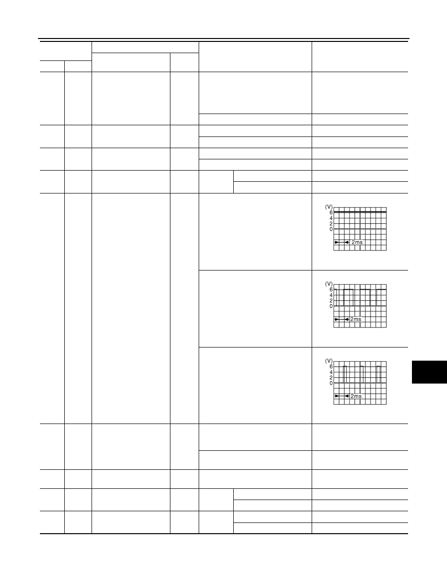
(V)
Ground
Power generation com-
mand signal
Output
Ignition switch ON
6.3 V
40% is set on “ACTIVE TEST”, “AL-
TERNATOR DUTY” of “ENGINE”
3.8 V
80% is set on “ACTIVE TEST”, “AL-
TERNATOR DUTY” of “ENGINE”
1.4 V
77
(L)
Ground
Fuel pump relay control
Output
• Approximately 1 second after turning
the ignition switch ON
• Engine running
0 - 1.0 V
Approximately 1 second or more after
turning the ignition switch ON
Battery voltage
80
(W)
Ground
Starter motor
Output
At engine cranking
Battery voltage
83
(R)
Ground
Headlamp LO (RH)
Output
Ignition
switch ON
Lighting switch OFF
0 V
Lighting switch 2ND
Battery voltage
84
(P)
Ground
Headlamp LO (LH)
Output
Ignition
switch ON
Lighting switch OFF
0 V
Lighting switch 2ND
Battery voltage
Terminal No.
(Wire color)
Description
Condition
Value
(Approx.)
Signal name
Input/
Output
+
−
JPMIA0001GB
JPMIA0002GB
JPMIA0003GB