Content .. 1430 1431 1432 1433 ..
Infiniti G35 (V35) Sedan. Manual - part 1432
WCS-12
< FUNCTION DIAGNOSIS >
DIAGNOSIS SYSTEM (UNIFIED METER AND A/C AMP.)
DIAGNOSIS SYSTEM (UNIFIED METER AND A/C AMP.)
CONSULT-III Function (METER/M&A)
INFOID:0000000000964484
CONSULT-III APPLICATION ITEMS
CONSULT-III can perform the following diagnosis modes with CAN communication with the unified meter and
A/C amp.
SELF DIAG RESULT
.
DATA MONITOR
Display Item List
X: Applicable
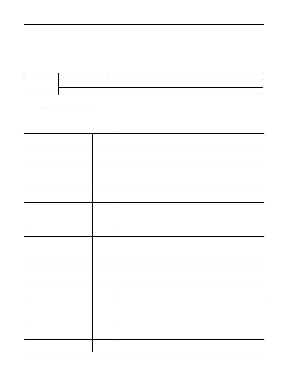
System
Diagnosis mode
Description
METER/M&A
Self Diagnostic Result
Unified meter and A/C amp. checks the conditions and displays memorized error.
Data Monitor
Displays unified meter and A/C amp. input/output data in real time.
Display item [Unit]
MAIN
SIGNALS
Description
SPEED METER
[km/h]
X
Value of vehicle speed signal received from ABS actuator and electric unit (control
unit) with CAN communication line.
NOTE:
655.35 is displayed when the malfunction signal is received.
SPEED OUTPUT
[km/h]
X
Vehicle speed signal value transmitted to other units with CAN communication
line.
NOTE:
655.35 is displayed when the malfunction signal is received.
ODO OUTPUT
[km/h or mph]
Odometer signal value transmitted to other units with CAN communication line.
TACHO METER
[rpm]
X
Value of the engine speed signal received from ECM with CAN communication
line.
NOTE:
8191.875 is displayed when the malfunction signal is received.
FUEL METER
[lit.]
X
Fuel level indicated on combination meter.
W TEMP METER
[
°
C]
X
Value of engine coolant temperature signal received from ECM with CAN commu-
nication line.
NOTE:
215 is displayed when the malfunction signal is input.
ABS W/L
[On/Off]
Status of ABS warning lamp judged from ABS warning lamp signal received from
ABS actuator and electric unit (control unit) with CAN communication line.
VDC/TCS IND
[On/Off]
Status of VDC indicator lamp judged from VDC OFF indicator lamp signal re-
ceived from ABS actuator and electric unit (control unit) with CAN communication
line.
SLIP IND
[On/Off]
Status of slip indicator lamp judged from slip indicator lamp signal received from
ABS actuator and electric unit (control unit) with CAN communication line.
BRAKE W/L
[On/Off]
Status of brake warning lamp judged from brake warning lamp signal received
from ABS actuator and electric unit (control unit) with CAN communication line.
NOTE:
Displays “Off” if the brake warning lamp is illuminated when the valve check starts,
the parking brake switch is turned ON or the brake fluid level switch is turned ON.
DOOR W/L
[On/Off]
Status of door warning judged from door switch signal received from BCM with
CAN communication line.
TRUNK/GLAS-H
[On/Off]
Status of trunk warning judged from trunk switch signal received from BCM with
CAN communication line.