Infiniti G35 (V35) Sedan. Manual - part 1428


  Index      Infiniti     Infiniti G35 (V35) Sedan - service repair manual 2007 year


Search            


Content   ..  1426  1427  1428  1429   ..


Infiniti G35 (V35) Sedan. Manual - part 1428


VTL-50

< ON-VEHICLE REPAIR >

DUCTS AND GRILLES

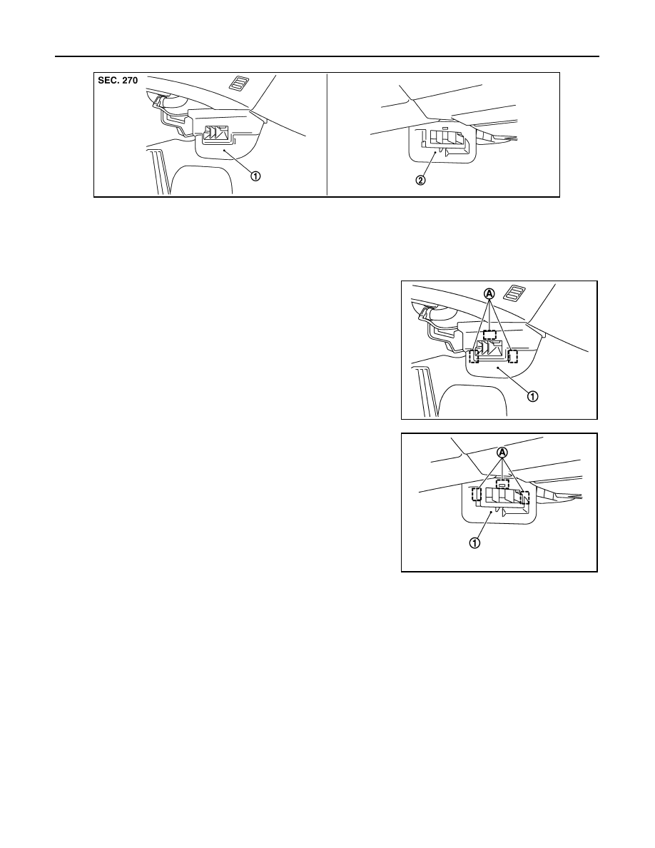
FOOT GRILLES : Removal and Installation

INFOID:0000000000959827

REMOVAL

1.

Remove mounting clips (A), and then remove foot grille (left) (1).

2.

Remove mounting clips (A), and then remove foot grille (right)
(1).

INSTALLATION

Installation is basically the reverse order of removal.

FOOT DUCTS

FOOT DUCTS : Exploded View

INFOID:0000000000959828

1.

Foot grille (left)

2.

Foot grille (right)

JSIIA0217ZZ

JSIIA0040ZZ

JSIIA0041ZZ

DUCTS AND GRILLES

VTL-51

< ON-VEHICLE REPAIR >

C

D

E

F

G

H

J

K

L

M

A

B

VTL

N

O

P

1.

Aspirator

2.

Aspirator hose

3.

Front heater duct

4.

Foot duct (left)

5.

Defroster seal

6.

Packing

7.

Ventilator seal

8.

Ventilator door (left)

9.

Ventilator door (right)

10.

Foot duct (right)

11.

Defroster door lever

12. Foot door lever

13.

Ventilator door lever

14.

Ventilator door link

15. Main link

16.

Mode door motor bracket

17.

Mode door motor

18. Air mix door motor (passenger side)

19.

Intake sensor

20.

Intake sensor bracket

21. O-ring

22.

Low-pressure pipe 1

23.

High-pressure pipe 2

24. Expansion valve

25.

Cooler pipe grommet

26.

Insulator

27. Evaporator cover adapter

28.

Heater pipe bracket

29.

Case packing

30. Heater & cooling unit case (left)

31.

Heater pipe grommet

32.

Heater core

33. Air mix door motor (driver side)

*

34.

Foot door (left)

35.

Rear ventilator door

36. Foot door (right)

37.

Max. cool door lever

38.

Foot door link

39. Defroster door link

40.

Max. cool door link

41.

Main link sub

42. Evaporator cover

43.

Heater & cooling unit case (right)

44.

Evaporator

45. Drain hose

46.

Clamp

47.

Air mix door (Slide door)

48. Air mix door adapter

JSIIA0016GB

VTL-52

< ON-VEHICLE REPAIR >

DUCTS AND GRILLES

FOOT DUCTS : Removal and Installation

INFOID:0000000000959829

REMOVAL

1.

Remove heater & cooling unit assembly. Refer to 

VTL-35, "Removal and Installation"

.

2.

Remove mounting screws (A), and then remove heater pipe
cover (1).

3.

Remove mounting screws (B), and then remove foot duct (left)
(2).

4.

Remove air mix door motor (passenger side). Refer to 

VTL-41, "Removal and Installation"

.

5.

Remove mode door motor. Refer to 

VTL-39, "Removal and Installation"

.

6.

Remove mounting screws (A), and then remove evaporator
cover (1).

7.

Remove mounting screws (B), and then remove foot duct (right)
(2).

INSTALLATION

Installation is basically the reverse order of removal.

REAR FLOOR DUCT 1 (WITHOUT REAR VENTILATOR)

REAR FLOOR DUCT 1 (WITHOUT REAR VENTILATOR) : Exploded View

INFOID:0000000000959830

49. Heater pipe cover

50.

Max. cool door (left)

51.

Defroster door (left)

52. Center case

53.

Defroster door (right)

54.

Max. cool door (right)

*

With left and right ventilation temperature separately system.

Refer to 

GI-4, "Components"

 for symbols in the figure.

JSIIA0106ZZ

JSIIA0107ZZ

DUCTS AND GRILLES

VTL-53

< ON-VEHICLE REPAIR >

C

D

E

F

G

H

J

K

L

M

A

B

VTL

N

O

P

REAR FLOOR DUCT 1 (WITHOUT REAR VENTILATOR) : Removal and Installation

INFOID:0000000000959831

REMOVAL

1.

Remove center console. Refer to 

IP-12, "Removal and Installation"

.

2.

Remove Instrument side panel (RH). Refer to 

IP-12, "Removal and Installation"

.

3.

Remove AV control unit. Refer to 

AV-111, "Removal and Installation"

 (BASE AUDIO WITHOUT NAVIGA-

TION), 

AV-292, "Removal and Installation"

 (BOSE AUDIO WITHOUT NAVIGATION), 

AV-530, "Removal

and Installation"

 (BOSE AUDIO WITH NAVIGATION).

4.

Remove mounting clip (A).

5.

Remove mounting clip (B), and then peel back floor carpet to a
point where rear floor duct 1 is visible.

6.

Remove rear floor duct 1 to rightward.

INSTALLATION

Installation is basically the reverse order of removal.

REAR FLOOR DUCT 1 & REAR VENTILATOR DUCT 1(WITH REAR VENTILA-
TOR)

REAR FLOOR DUCT 1 & REAR VENTILATOR DUCT 1(WITH REAR VENTILATOR) 
: Exploded View

INFOID:0000000000959832

1.

Rear floor duct 1 (without rear venti-
lator)

2.

Rear floor duct 2 (left)

3.

Rear floor duct 2 (right)

4.

Rear floor duct 1& rear ventilator 
duct 1

5.

Rear ventilator duct 2

6.

Console mask

7.

Rear ventilator grille (Console lid as-
sembly)

A.

With rear ventilator

JSIIA0019ZZ

JSIIA0074ZZ


Content   ..  1426  1427  1428  1429   ..