Infiniti G35 (V35) Sedan. Manual - part 135
AV-312
< ON-VEHICLE REPAIR >
[BOSE AUDIO WITHOUT NAVIGATION]
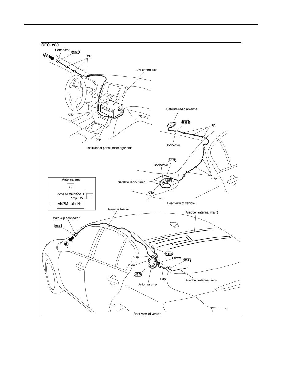
ANTENNA FEEDER (SATELLITE RADIO)
ANTENNA FEEDER (SATELLITE RADIO)
Harness Layout
INFOID:0000000000964756
JSNIA0161GB
|
|
|
AV-312 < ON-VEHICLE REPAIR > [BOSE AUDIO WITHOUT NAVIGATION] ANTENNA FEEDER (SATELLITE RADIO) ANTENNA FEEDER (SATELLITE RADIO) Harness Layout INFOID:0000000000964756 JSNIA0161GB |