Content .. 1105 1106 1107 1108 ..
Infiniti G35 (V35) Sedan. Manual - part 1107
REAR DRIVE SHAFT
RAX-13
< ON-VEHICLE REPAIR >
C
E
F
G
H
I
J
K
L
M
A
B
RAX
N
O
P
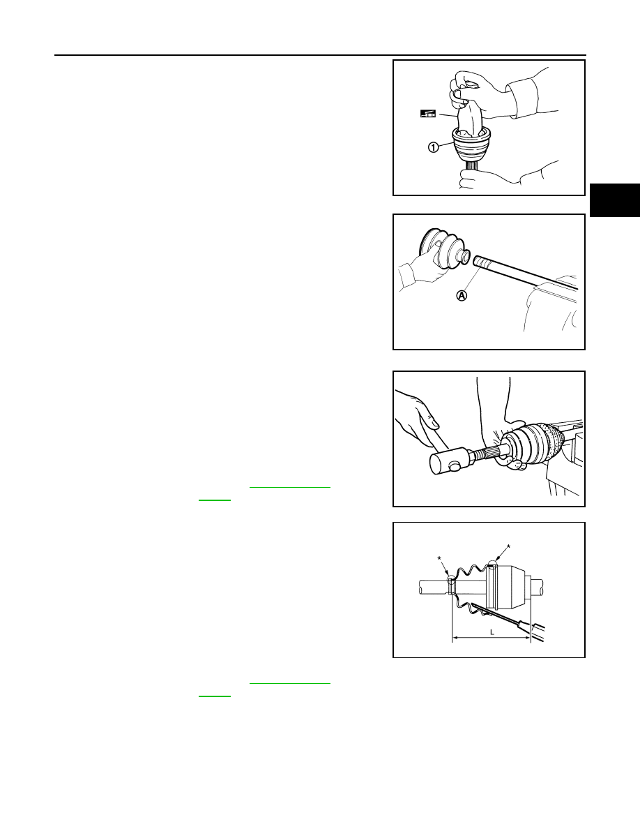
1.
Apply the specified amount of grease into joint sub-assembly (1)
serration hole until grease begins to ooze from ball groove and
serration hole.
CAUTION:
After applying grease, use a shop cloth to wipe off old
grease that has oozed out.
2.
Wrap serrated part of shaft with tape (A). Install boot band and
boot to shaft. Be careful not to damage boot.
CAUTION:
Never reuse boot and boot band.
3.
Remove the tape wrapped around the serrated on shaft.
4.
Position circular clip on groove at the shaft edge.
CAUTION:
Never reuse circular clip.
NOTE:
Drive joint inserter is recommended when installing circular clip.
5.
Align both center axles of the shaft edge and joint sub-assembly.
Then assemble shaft with circular clip joint sub-assembly.
6.
Install joint sub-assembly to shaft using plastic hammer.
CAUTION:
Confirm that joint sub-assembly is correctly engaged while
rotating drive shaft.
7.
Apply the balance of the specified amount of grease into the
boot inside from large diameter side of boot.
8.
Install the boot securely into grooves (indicated by “*” marks)
shown in the figure.
CAUTION:
If grease adheres to the boot mounting surface (with “*”
mark) on the shaft or housing, boot may come off. Remove
all grease from the surfaces.
9.
To prevent from deformation of the boot, adjust the boot installa-
tion length to the specified value shown below (L) by inserting
the suitable tool into inside of the boot from the large diameter
side of boot and discharging the inside air.
CAUTION:
• If the boot installation length is outside the standard, it may cause breakage in boot.
• Be careful not to touch the inside of the boot with the tip of tool.
JPDIF0008ZZ
Standard
Grease amount
: Refer to
.
JPDIF0009ZZ
RAC0049D
Standard
Boots installed
length (L)
: Refer to
.
JPDIF0018ZZ