Content .. 1104 1105 1106 1107 ..
Infiniti G35 (V35) Sedan. Manual - part 1106
REAR DRIVE SHAFT
RAX-9
< ON-VEHICLE REPAIR >
C
E
F
G
H
I
J
K
L
M
A
B
RAX
N
O
P
REAR DRIVE SHAFT
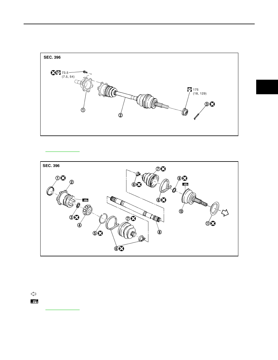
Exploded View
INFOID:0000000000957508
Removal and Installation
INFOID:0000000000957509
REMOVAL
1.
Remove tire from vehicle with power tool.
2.
Remove cotter pin, then loosen hub lock nut with power tool.
1.
Side flange
2.
Drive shaft
3.
Cotter pin
Refer to
1.
Plug
2.
Housing
3.
Snap ring
4.
Ball cage/steel ball/inner race as-
sembly
5.
Stopper ring
6.
Boot band
7.
Boot
8.
Shaft
9.
Circular clip
10. Joint sub-assembly
11.
Dust shield
: Wheel side
: NISSAN genuine grease or an equivalent.
Refer to
for symbols not described on the above.
JPDIG0002GB
JPDIG0003ZZ