Content .. 1015 1016 1017 1018 ..
Infiniti G35 (V35) Sedan. Manual - part 1017
PCS-122
< ON-VEHICLE REPAIR >
[POWER DISTRIBUTION SYSTEM]
PUSH BUTTON IGNITION SWITCH
PUSH BUTTON IGNITION SWITCH
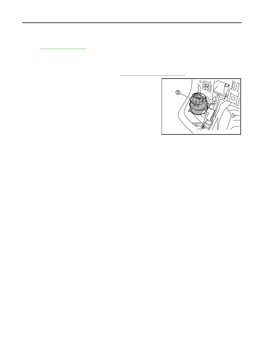
Exploded View
INFOID:0000000000964261
.
Removal and Installation
INFOID:0000000000964262
REMOVAL
1.
Remove the cluster lid A assembly. Refer to
IP-12, "Removal and Installation"
2.
Remove the push-button ignition switch (1) from cluster lid A
assembly, and then remove pawl (A). Press push-button ignition
switch (1) back to disengage from cluster lid A assembly.
INSTALLATION
Install in the reverse order of removal.
JMKIA0167ZZ