Infiniti G35 (V35). Manual - part 413
 

  Index      Infiniti     Infiniti G35 (V35) Coupe - service repair manual 2007 year


Search            


Content   ..  411  412  413  414   ..


Infiniti G35 (V35). Manual - part 413


DTC P1217 ENGINE OVER TEMPERATURE

EC-533

C

D

E

F

G

H

I

J

K

L

M

A

EC

2. 

DETECT MALFUNCTIONING PART

Check the following.

●

Harness for open or short between cooling fan motors-1, 2 and IPDM E/R

●

Harness for open or short between cooling fan motors-1, 2 and ground

●

Harness for open or short between IPDM E/R and ground

>> Repair open circuit or short to ground or short to power in harness connectors.

3. 

CHECK COOLING FAN MOTORS

Refer to 

EC-534, "Component Inspection"

 .

OK or NG

OK

>> GO TO 4.

NG

>> Replace malfunctioning cooling fan motors.

4. 

CHECK INTERMITTENT INCIDENT

Perform 

EC-151, "TROUBLE DIAGNOSIS FOR INTERMITTENT INCIDENT"

 .

OK or NG

OK

>> Replace IPDM E/R. Refer to 

PG-16, "IPDM E/R (INTELLIGENT POWER DISTRIBUTION MOD-

ULE ENGINE ROOM)"

 .

NG

>> Repair or replace harness or connectors.

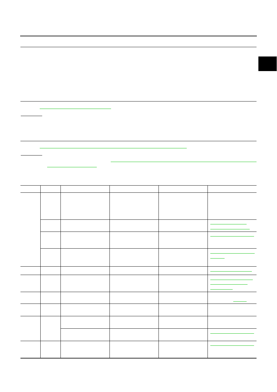
Main 12 Causes of Overheating

NBS000XH

Engine

Step

Inspection item

Equipment

Standard

Reference page

OFF

1

●

Blocked radiator

●

Blocked condenser

●

Blocked radiator grille

●

Blocked bumper

●

Visual

No blocking

—

2

●

Coolant mixture

●

Coolant tester

50 - 50% coolant mixture

MA-11, "Anti-Freeze 
Coolant Mixture Ratio"

3

●

Coolant level

●

Visual

Coolant up to MAX level 
in reservoir tank and radi-
ator filler neck

CO-10, "LEVEL CHECK"

4

●

Radiator cap

●

Pressure tester

59 - 98 kPa

(0.6 - 1.0 kg/cm

2

 , 9 - 14 

psi) (Limit)

CO-15, "Checking Radia-
tor Cap"

ON*

2

5

●

Coolant leaks

●

Visual

No leaks

CO-10, "LEAK CHECK"

ON*

2

6

●

Thermostat

●

Touch the upper and 
lower radiator hoses

Both hoses should be hot

CO-28, "WATER INLET 
AND THERMOSTAT 
ASSEMBLY"

ON*

1

7

●

Cooling fan

●

CONSULT-II

Operating

See trouble diagnosis for 
DTC P1217 (

EC-523

 ).

OFF

8

●

Combustion gas leak

●

Color checker chemical 
tester 4 Gas analyzer

Negative

—

ON*

3

9

●

Coolant temperature 
gauge

●

Visual

Gauge less than 3/4 
when driving

—

●

Coolant overflow to 
reservoir tank

●

Visual

No overflow during driving 
and idling

CO-10, "LEVEL CHECK"

OFF*

4

10

●

Coolant return from 
reservoir tank to radia-
tor

●

Visual

Should be initial level in 
reservoir tank

CO-10, "LEVEL CHECK"

EC-534

DTC P1217 ENGINE OVER TEMPERATURE

*1: Turn the ignition switch ON.
*2: Engine running at 3,000 rpm for 10 minutes.
*3: Drive at 90 km/h (55 MPH) for 30 minutes and then let idle for 10 minutes.
*4: After 60 minutes of cool down time.
For more information, refer to 

CO-6, "OVERHEATING CAUSE ANALYSIS"

 .

Component Inspection

NBS000XI

COOLING FAN MOTORS-1 AND -2

1.

Disconnect cooling fan motor harness connectors.

2.

Supply cooling fan motor terminals with battery voltage and
check operation.

Cooling fan motor should operate.

If NG, replace cooling fan motors.

OFF

11

●

Cylinder head

●

Straight gauge feeler 
gauge

0.1 mm (0.004 in) Maxi-
mum distortion (warping)

EM-119, "CYLINDER 
HEAD"

12

●

Cylinder block and pis-
tons

●

Visual

No scuffing on cylinder 
walls or piston

EM-137, "CYLINDER 
BLOCK"

Engine

Step

Inspection item

Equipment

Standard

Reference page

Speed

terminals

(+)

(

−

)

Cooling fan motor

Low 

1

4

2

3

High

1 and 2

3 and 4

SEF734W

DTC P1225 TP SENSOR

EC-535

C

D

E

F

G

H

I

J

K

L

M

A

EC

DTC P1225 TP SENSOR

PFP:16119

Component Description

NBS000XJ

Electric throttle control actuator consists of throttle control motor,
throttle position sensor, etc. The throttle position sensor responds to
the throttle valve movement. 
The throttle position sensor has two sensors. These sensors are a
kind of potentiometers which transform the throttle valve position into
output voltage, and emit the voltage signal to the ECM. In addition,
these sensors detect the opening and closing speed of the throttle
valve and feed the voltage signals to the ECM. The ECM judges the
current opening angle of the throttle valve from these signals and the
ECM controls the throttle control motor to make the throttle valve
opening angle properly in response to driving condition.

On Board Diagnosis Logic

NBS000XK

The MIL will not light up for this self-diagnosis.

DTC Confirmation Procedure

NBS000XL

NOTE:
If DTC Confirmation Procedure has been previously conducted, always turn ignition switch OFF and wait at
least 10 seconds before conducting the next test.
TESTING CONDITION:
Before performing the following procedure, confirm that battery voltage is more than 10V at idle.

 WITH CONSULT-II

1.

Turn ignition switch ON.

2.

Select “DATA MONITOR” mode with CONSULT-II.

3.

Turn ignition switch OFF and wait at least 10 seconds.

4.

Turn ignition switch ON.

5.

If 1st trip DTC is detected, go to 

EC-536, "Diagnostic Procedure"

.

 WITH GST

Follow the procedure “WITH CONSULT-II” above.

PBIB0145E

DTC No.

Trouble diagnosis name

DTC detecting condition

Possible cause

P1225
1225

Closed throttle position 
learning performance

Closed throttle position learning value is exces-
sively low.

●

Electric throttle control actuator
(TP sensor 1 and 2)

SEF058Y

EC-536

DTC P1225 TP SENSOR

Diagnostic Procedure

NBS000XM

1. 

CHECK ELECTRIC THROTTLE CONTROL ACTUATOR VISUALLY

1.

Turn ignition switch OFF.

2.

Remove the intake air duct.

3.

Check if foreign matter is caught between the throttle valve and
the housing.

OK or NG

OK

>> GO TO 2.

NG

>> Remove the foreign matter and clean the electric throttle

control actuator inside.

2. 

REPLACE ELECTRIC THROTTLE CONTROL ACTUATOR

1.

Replace the electric throttle control actuator.

2.

Perform 

EC-79, "Throttle Valve Closed Position Learning"

 .

3.

Perform 

EC-79, "Idle Air Volume Learning"

 .

>> INSPECTION END

Removal and Installation

NBS000XN

ELECTRIC THROTTLE CONTROL ACTUATOR

Refer to 

EM-18, "INTAKE MANIFOLD COLLECTOR"

 .

PBIB1015E


Content   ..  411  412  413  414   ..