Infiniti G35 (V35). Manual - part 412
 

  Index      Infiniti     Infiniti G35 (V35) Coupe - service repair manual 2007 year


Search            


Content   ..  410  411  412  413   ..


Infiniti G35 (V35). Manual - part 412


DTC P1217 ENGINE OVER TEMPERATURE

EC-529

C

D

E

F

G

H

I

J

K

L

M

A

EC

Diagnostic Procedure

NBS000XG

1. 

INSPECTION START

Do you have CONSULT-II?
Yes or No

Yes

>> GO TO 2.

No

>> GO TO 4.

2. 

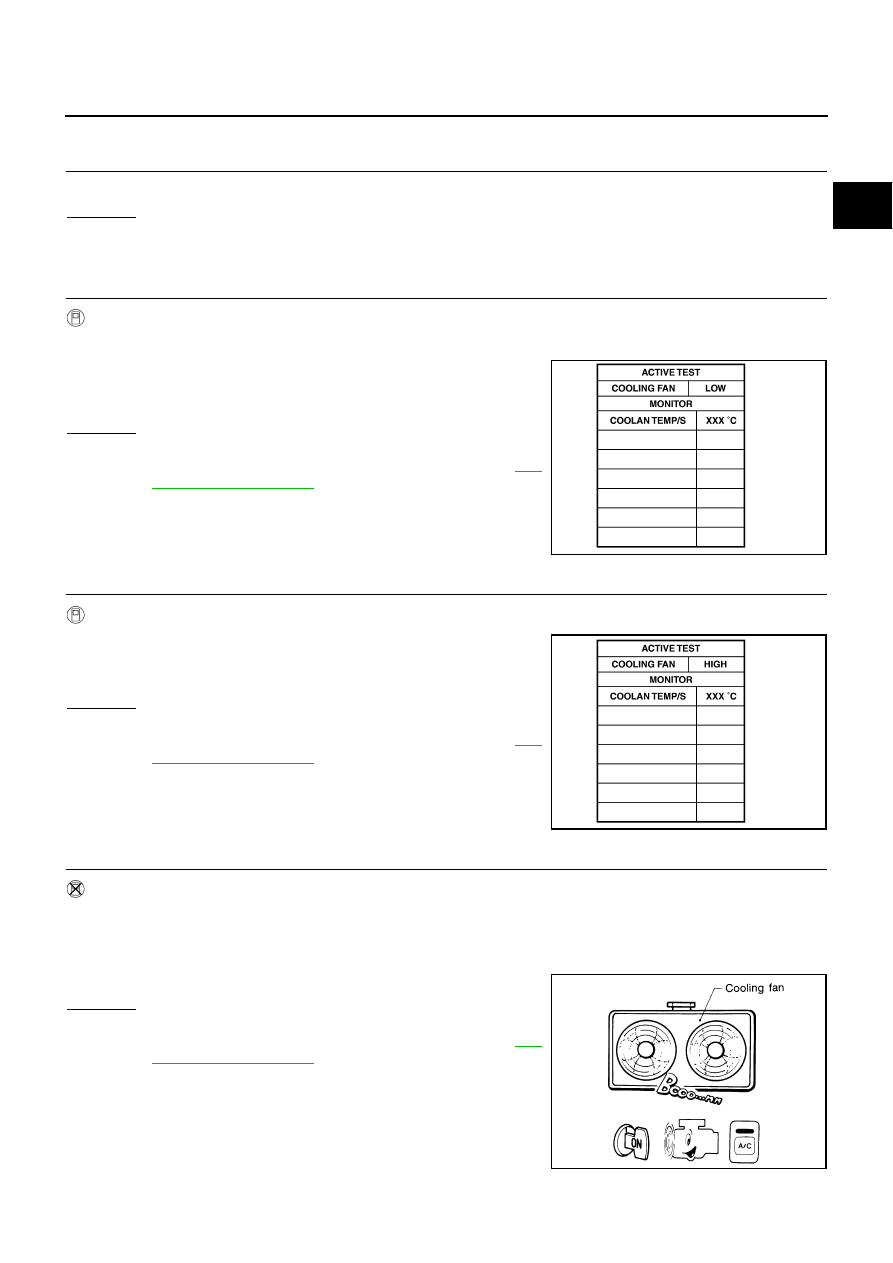
CHECK COOLING FAN LOW SPEED OPERATION

 With CONSULT-II

1.

Start engine and let it idle.

2.

Select “COOLING FAN” in “ACTIVE TEST” mode with CON-
SULT-II and touch “LOW” on the CONSULT-II screen.

3.

Make sure that cooling fans-1 and -2 operate at low speed.

OK or NG

OK

>> GO TO 3.

NG

>> Check cooling fan low speed control circuit. (Go to 

EC-

531, "PROCEDURE A"

 .)

3. 

CHECK COOLING FAN HIGH SPEED OPERATION

 With CONSULT-II

1.

Touch “HIGH” on the CONSULT-II screen.

2.

Make sure that cooling fans-1 and -2 operate at higher speed
than low speed.

OK or NG

OK

>> GO TO 6.

NG

>> Check cooling fan high speed control circuit. (Go to 

EC-

532, "PROCEDURE B"

 .)

4. 

CHECK COOLING FAN LOW SPEED OPERATION

 Without CONSULT-II

1.

Start engine and let it idle.

2.

Turn air conditioner switch ON.

3.

Turn blower fan switch ON.

4.

Make sure that cooling fans-1 and -2 operate at low speed.

OK or NG

OK

>> GO TO 5.

NG

>> Check cooling fan low speed control circuit. (Go to 

EC-

531, "PROCEDURE A"

 .)

SEF784Z

SEF785Z

SEC163BA

EC-530

DTC P1217 ENGINE OVER TEMPERATURE

5. 

CHECK COOLING FAN HIGH SPEED OPERATION

 Without CONSULT-II

1.

Turn ignition switch OFF.

2.

Turn air conditioner switch and blower fan switch OFF.

3.

Disconnect engine coolant temperature sensor harness connector.

4.

Connect 150

Ω

 resistor to engine coolant temperature sensor harness connector.

5.

Restart engine and make sure that cooling fans-1 and -2 oper-
ate at higher speed than low speed.

OK or NG

OK

>> GO TO 6.

NG

>> Check cooling fan high speed control circuit. (Go to 

EC-

532, "PROCEDURE B"

 .)

6. 

CHECK COOLING SYSTEM FOR LEAK

Refer to 

CO-10, "LEAK CHECK"

 .

OK or NG

OK

>> GO TO 7.

NG

>> Check the following for leak.

●

Hose

●

Radiator

●

Water pump

7. 

CHECK RADIATOR CAP

Refer to 

CO-15, "Checking Radiator Cap"

 .

OK or NG

OK

>> GO TO 8.

NG

>> Replace radiator cap.

8. 

CHECK THERMOSTAT

Refer to 

CO-28, "WATER INLET AND THERMOSTAT ASSEMBLY"

 .

OK or NG

OK

>> GO TO 9.

NG

>> Replace thermostat

9. 

CHECK ENGINE COOLANT TEMPERATURE SENSOR

Refer to 

EC-231, "Component Inspection"

 .

OK or NG

OK

>> GO TO 10.

NG

>> Replace engine coolant temperature sensor.

10. 

CHECK MAIN 12 CAUSES

If the cause cannot be isolated, go to 

EC-533, "Main 12 Causes of Overheating"

 .

>> INSPECTION END

MEC475B

DTC P1217 ENGINE OVER TEMPERATURE

EC-531

C

D

E

F

G

H

I

J

K

L

M

A

EC

PROCEDURE A

1. 

CHECK POWER SUPPLY CIRCUIT

1.

Turn ignition switch OFF.

2.

Disconnect IPDM E/R harness connector E6.

3.

Check voltage between IPDM E/R terminals 15, 16 and ground
with CONSULT-II or tester.

OK or NG

OK

>> GO TO 3.

NG

>> GO TO 2.

2. 

DETECT MALFUNCTIONING PART

Check the following.

●

40A fusible links

●

Harness for open or short between IPDM E/R and battery

>> Repair open circuit or short to ground or short to power in harness or connectors.

3. 

CHECK COOLING FAN MOTORS CIRCUIT

1.

Disconnect cooling fan motor-1 harness connector and cooling
fan motor-2 harness connector.

2.

Disconnect all IPDM E/R harness connectors.

3.

Check harness continuity between the following;
cooling fan motor-1 terminal 2 and IPDM E/R terminal 11,
cooling fan motor-1 terminal 3 and ground.
IPDM E/R terminal 38, 60 and ground.
Refer to wiring diagram.

4.

Also check harness for short to ground and short to power.

5.

Check harness continuity between the following;
cooling fan motor-2 terminal 2 and IPDM E/R terminal 10,
cooling fan motor-2 terminal 3 and ground.
Refer to wiring diagram.

6.

Also check harness for short to ground and short to power.

OK or NG

OK

>> GO TO 5.

NG

>> GO TO 4.

Voltage: Battery voltage

PBIB1924E

Continuity should exist.

Continuity should exist.

PBIB1283E

EC-532

DTC P1217 ENGINE OVER TEMPERATURE

4. 

DETECT MALFUNCTIONING PART

Check the following.

●

Harness for open or short between cooling fan motors-1, 2 and IPDM E/R

●

Harness for open or short between cooling fan motors-1, 2 and ground

●

Harness for open or short between IPDM E/R and ground

>> Repair open circuit or short to ground or short to power in harness connectors.

5. 

CHECK COOLING FAN MOTORS

Refer to 

EC-534, "Component Inspection"

 .

OK or NG

OK

>> GO TO 6.

NG

>> Replace malfunctioning cooling fan motors.

6. 

CHECK INTERMITTENT INCIDENT

Perform 

EC-151, "TROUBLE DIAGNOSIS FOR INTERMITTENT INCIDENT"

 .

OK or NG

OK

>> Replace IPDM E/R. Refer to 

PG-16, "IPDM E/R (INTELLIGENT POWER DISTRIBUTION MOD-

ULE ENGINE ROOM)"

 .

NG

>> Repair or replace harness or connector. 

PROCEDURE B

1. 

CHECK COOLING FAN MOTORS CIRCUIT

1.

Turn ignition switch OFF.

2.

Disconnect cooling fan motor-1 harness connector and cooling
fan motor-2 harness connector.

3.

Disconnect IPDM E/R harness connectors E5, E6.

4.

Check harness continuity between the following;
cooling fan motor-1 terminal 1 and IPDM E/R terminal 8,
cooling fan motor-1 terminal 4 and IPDM E/R terminal 9,
IPDM E/R terminal 14, 38, 60 and ground.
Refer to wiring diagram.

5.

Also check harness for short to ground and short to power.

6.

Check harness continuity between the following;
cooling fan motor-2 terminal 1 and IPDM E/R terminal 13,
cooling fan motor-2 terminal 4 and IPDM E/R terminal 12.
Refer to wiring diagram.

7.

Also check harness for short to ground and short to power.

OK or NG

OK

>> GO TO 3.

NG

>> GO TO 2.

Continuity should exist.

Continuity should exist.

PBIB1283E


Content   ..  410  411  412  413   ..