Infiniti G20 (P11). Manual - part 531
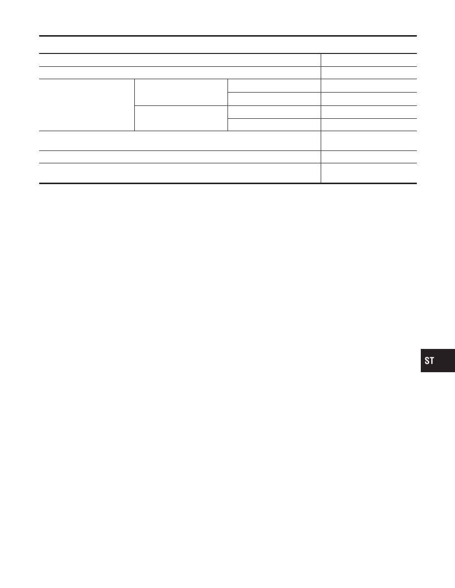
Power Steering
NCST0036
Applied model
All
Steering gear type
PR24AC
Rack sliding force
N (kg, lb)
Under normal operating oil pres-
sure
Range within
±
11.5 mm (
±
0.453 in)
from the neutral position at rack
speed of 3.5 mm (0.138 in)/s
Average force
167 - 226 (17 - 23, 37 - 51)
Maximum force deviation
98 (10, 22)
Except for the above range
Maximum sliding force
294 (30, 66)
Maximum force deviation
147 (15, 33)
Steering wheel turning force
(Measured at one full turn from the neutral position)
N (kg, lb)
39 (4, 9) or less
Fluid capacity (Approximate)
(US qt, Imp qt)
0.9 (1, 3/4)
Oil pump maximum pressure
kPa (kg/cm
2
, psi)
8,140 - 8,728 (83 - 89, 1,180 -
1,266)
GI
MA
EM
LC
EC
FE
CL
MT
AT
AX
SU
BR
RS
BT
HA
SC
EL
IDX
SERVICE DATA AND SPECIFICATIONS (SDS)
Power Steering
ST-33