Infiniti G20 (P11). Manual - part 504


  Index      Infiniti     Infiniti G20 (P11) - service repair manual 1999-2002 year


Search            


Content   ..  502  503  504  505   ..


Infiniti G20 (P11). Manual - part 504


SRS276

INSTALLATION

NCRS0017

1.

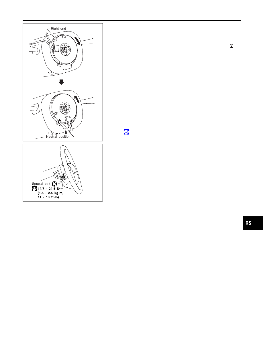
Set the front wheels in the straight-ahead position.

2.

Make sure that the spiral cable is in the neutral position.
The neutral position is detected by turning left about 2.5 revo-
lutions from the right end position. Align the two marks (

).

CAUTION:

I

The spiral cable may snap due to steering operation if the
cable is installed in an improper position.

I

Also, with the steering linkage disconnected, the cable
may snap by turning the steering wheel beyond the limited
number of turns. The spiral cable can be turned to the left
about 2.5 turns from the right end position.

3.

Connect spiral cable connector and tighten with screws. Install
steering column cover.

4.

Install steering wheel, aligning with spiral cable pin guides, and
pull spiral cable through.

5.

Connect horn connector and engage spiral cable with pawls in
steering wheel. Move air bag module connector away from
steering wheel lower lid opening.

6.

Tighten nut.

: 29 - 39 N·m (3.0 - 4.0 kg-m, 22 - 29 ft-lb)

7.

Install dynamic damper.

SBF812EJ

8.

Position air bag module and tighten with new special bolts.

9.

Connect air bag module connector.

10. Install steering switch and all lids.
11. Conduct self-diagnosis to ensure entire SRS operates prop-

erly. (Use CONSULT-II or warning lamp check.)
Before performing self-diagnosis, connect both battery cables.

12. Turn steering wheel to the left end and then to the right end

fully to make sure that spiral cable is set in the neutral posi-
tion.
If air bag warning lamp blinks or stays ON (at the user mode),
it shows the spiral cable may be snapped due to its improper
position. Perform self-diagnosis again (use CONSULT-II or
warning lamp). If a malfunction is detected, replace the spiral
cable with a new one.

13. Perform self-diagnosis again to check that no malfunction is

detected.

GI

MA

EM

LC

EC

FE

CL

MT

AT

AX

SU

BR

ST

BT

HA

SC

EL

IDX

SUPPLEMENTAL RESTRAINT SYSTEM (SRS)

Driver Air Bag Module and Spiral Cable (Cont’d)

RS-21

SRS568

Front Passenger Air Bag Module

SRS569-A

SRS945

REMOVAL

NCRS0018

CAUTION:

I

Before servicing SRS, turn the ignition switch off, discon-
nect both battery cables and wait for at least 3 minutes.

I

Always work from the side of or under air bag module.

1.

Open the glove box lid.

2.

Disconnect front passenger air bag module connector from air
bag harness connector.

3.

Remove glove box assembly. Refer to BT-23, “INSTRUMENT
PANEL ASSEMBLY” for details.

4.

Remove the nuts and hex bolts or special bolts using the
TAMPER RESISTANT TORX (Size T50) from front passenger
air bag module.
Take out the air bag module from the instrument panel.

I

The air bag module is heavy and should be supported using
both hands during removal.

SRS570

CAUTION:

I

Always place air bag module with pad side facing upward.

I

Do not attempt to disassemble air bag module.

I

Do not use old bolts after removal; replace with new bolts.

I

Do not insert any foreign objects (screwdriver, etc.) into
air bag module connector.

SBF814E

I

Replace air bag module if it has been dropped or sus-
tained an impact.

I

Do not expose the air bag module to temperatures exceed-
ing 90°C (194°F).

I

Do not allow oil, grease or water to come in contact with
the air bag module.

I

After air bag inflates, the front instrument panel assembly
should be replaced if damaged.

SUPPLEMENTAL RESTRAINT SYSTEM (SRS)

Front Passenger Air Bag Module

RS-22

SRS569-A

SRS945

INSTALLATION

NCRS0019

CAUTION:

I

Always work from the side of or under air bag module.

1.

Install front passenger air bag module on steering member.

I

Ensure harness is not caught between rear of air bag module
and steering member.

2.

Install glove box assembly. (Glove box lid is open.)

SRS568

3.

Connect air bag module connector to air bag harness connec-
tor.

4.

Close the glove box lid.

5.

Connect both battery cables.

6.

Conduct self-diagnosis to ensure entire SRS operates prop-
erly. (Use CONSULT-II or warning lamp check.)

SRS571

Side Air Bag Module

REMOVAL

NCRS0020

CAUTION:

I

Before servicing SRS, turn the ignition switch off, discon-
nect both battery cables and wait at least 3 minutes.

I

Always work from the rear of air bag module.

1.

Remove seatback board.

I

When using a clip removal tool to remove the seatback
finisher, take care not to damage the air bag harness.

2.

Disconnect side air bag module connector.

GI

MA

EM

LC

EC

FE

CL

MT

AT

AX

SU

BR

ST

BT

HA

SC

EL

IDX

SUPPLEMENTAL RESTRAINT SYSTEM (SRS)

Front Passenger Air Bag Module (Cont’d)

RS-23

SRS572-A

3.

Pull up the seatback trim.

4.

Remove the nuts securing the inner cloth which covers side air
bag module. Then pull up the inner cloth.

5.

Remove the screws securing the seatback finisher. Then
remove the seatback finisher.

6.

Remove the torx nuts coated with bonding agent from side air
bag module.

7.

Remove harness clips. Side air bag module can then be
removed.

SRS573

CAUTION:

I

Always place air bag module with the stud bolt side fac-
ing down.

I

Do not attempt to disassemble air bag module.

I

Do not use old nuts after removal; replace with new nuts.

I

Do not insert any foreign objects (screwdriver, etc.) into
air bag module connector.

SBF814E

I

Replace air bag module if it has been dropped or sus-
tained an impact.

I

Do not expose the air bag module to temperatures exceed-
ing 90°C (194°F).

I

Do not allow oil, grease or water to come in contact with
the air bag module.

I

After air bag inflates, the front seat should be replaced if
damaged.

SUPPLEMENTAL RESTRAINT SYSTEM (SRS)

Side Air Bag Module (Cont’d)

RS-24


Content   ..  502  503  504  505   ..