Infiniti G20 (P11). Manual - part 467


  Index      Infiniti     Infiniti G20 (P11) - service repair manual 1999-2002 year


Search            


Content   ..  465  466  467  468   ..


Infiniti G20 (P11). Manual - part 467


RHA069H

I

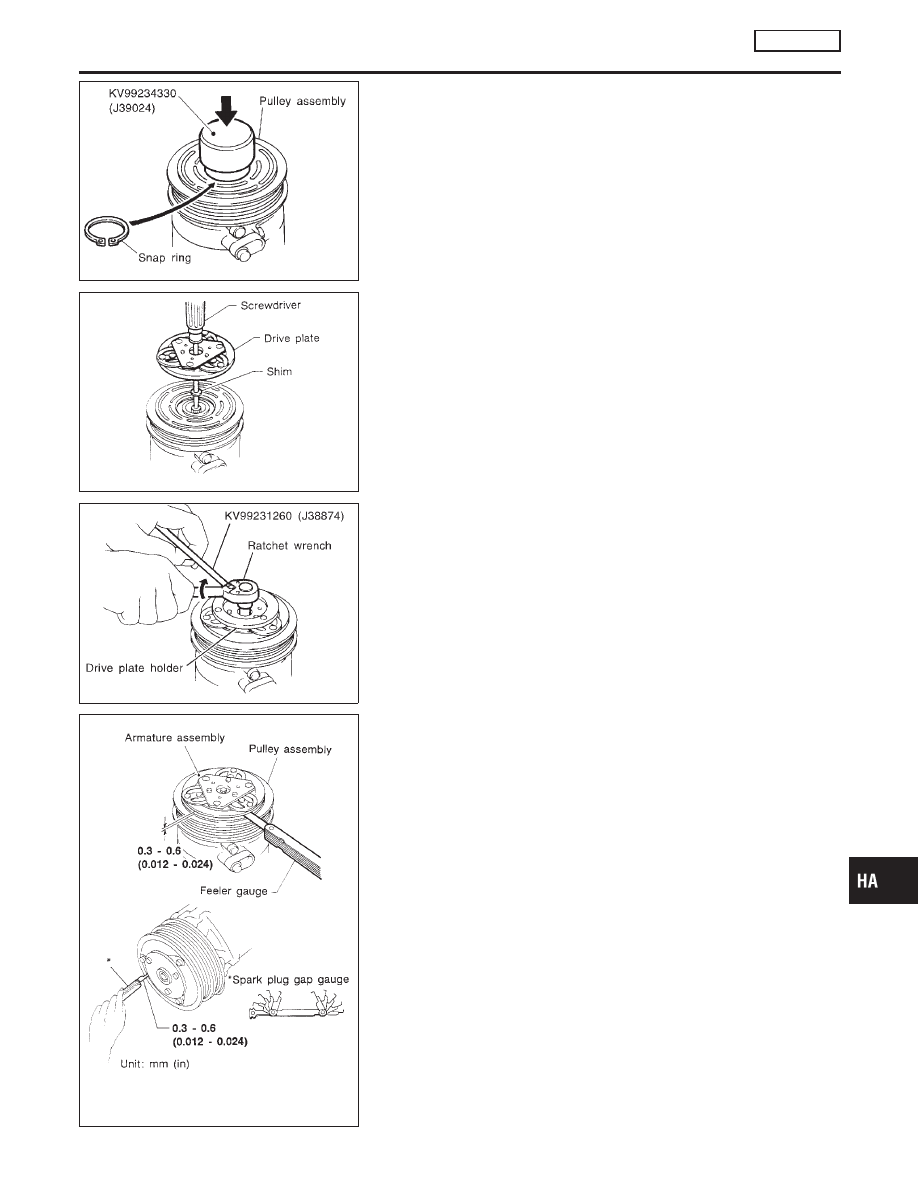
Install the pulley assembly using the installer and a hand
press, and then install the snap ring using snap ring pliers.

RHA078C

I

Install the drive plate on the drive shaft, together with the
original shim(s). Press the drive plate down by hand.

RHA070H

I

Using the holder to prevent drive plate rotation, tighten the bolt
to 12 to 15 N·m (1.2 to 1.5 kg-m, 9 to 11 ft-lb) torque.

I

After tightening the bolt, check that the pulley rotates
smoothly.

RHA080C

I

Check clearance all the way around the clutch disc.

Disc-to-pulley clearance:

0.3 - 0.6 mm (0.012 - 0.024 in)

If the specified clearance is not obtained, replace adjusting
spacer and readjust.

GI

MA

EM

LC

EC

FE

CL

MT

AT

AX

SU

BR

ST

RS

BT

SC

EL

IDX

SERVICE PROCEDURE

MANUAL

Compressor Clutch (Cont’d)

HA-199

Break-in Operation

NCHA0165S01

When replacing compressor clutch assembly, always conduct the
break-in operation. This is done by engaging and disengaging the
clutch about thirty times. Break-in operation raises the level of
transmitted torque.

RHA671H

Thermal Protector

INSPECTION

NCHA0166

I

When servicing, do not allow foreign matter to enter compres-
sor.

I

Check continuity between compressor harness terminal and
field coil.

Heater Unit (Heater Core)

REMOVAL

NCHA0193

RHA528H

1.

Drain the cooling system. Refer to MA-14, “Changing Engine
Coolant”.

2.

Discharge the A/C system. Refer to HA-191.

3.

Disconnect the two heater hoses from inside the engine com-
partment.

4.

Remove the cooling unit. Refer to HA-202.

5.

Remove the steering member assembly. Refer to BT-23, “Instru-
ment Panel Assembly”.

6.

Remove the heater unit.

7.

Remove the heater core.

SERVICE PROCEDURE

MANUAL

Compressor Clutch (Cont’d)

HA-200

INSTALLATION

NCHA0194

Install in the reverse order of removal.
When filling radiator with coolant, refer to MA-14, “Changing
Engine Coolant”.
Recharge the A/C system. Refer to HA-191.

Blower Unit

REMOVAL

NCHA0195

RHA529H

RHA530H

1.

Discharge the A/C system. Refer to HA-191.

2.

Disconnect the two refrigerant lines from the engine compart-
ment.
Cap the A/C lines to prevent moisture from entering the sys-
tem.

3.

Remove the glove box and mating trim. Refer to BT-23, “Instru-
ment Panel Assembly”.

4.

Remove cooling unit. Refer to HA-202.

5.

Disconnect the resistor and blower motor connector.

6.

Remove blower unit.

7.

Remove the three bolts and then remove the motor from the
blower case.

INSTALLATION

NCHA0196

Install in the reverse order of removal.
Recharge the A/C system. Refer to HA-191.

GI

MA

EM

LC

EC

FE

CL

MT

AT

AX

SU

BR

ST

RS

BT

SC

EL

IDX

SERVICE PROCEDURE

MANUAL

Heater Unit (Heater Core) (Cont’d)

HA-201

Cooling Unit (A/C Evaporator)

REMOVAL

NCHA0197

RHA531H

RHA532H

1.

Discharge the A/C system. Refer to HA-191.

2.

Disconnect the two refrigerant lines from the engine compart-
ment.
Cap the A/C lines to prevent moisture from entering the sys-
tem.

3.

Remove the glove box and mating trim. Refer to BT-23, “Instru-
ment Panel Assembly”.

4.

Disconnect the thermo control amp. connector.

5.

Remove the cooling unit.

6.

Separate the cooling unit case, and remove the evaporator.

INSTALLATION

NCHA0198

Installation is basically the reverse order of removal.
Recharge the A/C system. Refer to HA-191.

SERVICE PROCEDURE

MANUAL

Cooling Unit (A/C Evaporator)

HA-202


Content   ..  465  466  467  468   ..