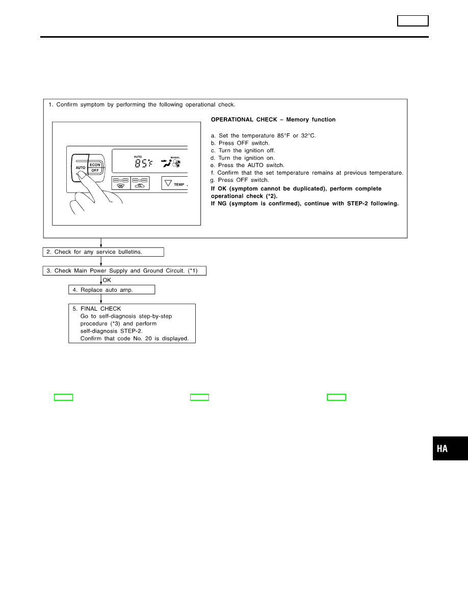
Infiniti G20 (P11). Manual - part 440


  Index      Infiniti     Infiniti G20 (P11) - service repair manual 1999-2002 year


Search            


Content   ..  438  439  440  441   ..


Infiniti G20 (P11). Manual - part 440


Memory Function

TROUBLE DIAGNOSIS PROCEDURE FOR MEMORY FUNCTION

=NCHA0102

SYMPTOM:

I

Memory function does not operate.

INSPECTION FLOW

RHA885H

*1: HA-46

*2: HA-42

*3: HA-32

GI

MA

EM

LC

EC

FE

CL

MT

AT

AX

SU

BR

ST

RS

BT

SC

EL

IDX

TROUBLE DIAGNOSES

AUTO

Memory Function

HA-91

ECON (ECONOMY) Mode

TROUBLE DIAGNOSIS PROCEDURE FOR ECON (ECONOMY) MODE

=NCHA0103

SYMPTOM:

I

ECON mode does not operate.

INSPECTION FLOW

SHA350F

*1: HA-45
*2: HA-42

*3: HA-32

*4: HA-46

RHA072H

Ambient Sensor Circuit

COMPONENT DESCRIPTION

NCHA0039

The ambient sensor is attached in front of the driver’s side con-
denser. It detects ambient temperature and converts it into a resis-
tance value which is then input into the auto amplifier.

TROUBLE DIAGNOSES

AUTO

ECON (ECONOMY) Mode

HA-92

AMBIENT TEMPERATURE INPUT PROCESS

NCHA0040

The automatic amplifier includes a “processing circuit” for the ambi-
ent sensor input. However, when the temperature detected by the
ambient sensor increases quickly, the processing circuit retards the
auto amp. function. It only allows the auto amp. to recognize an
ambient temperature increase of 0.33°C (0.6°F) per 100 seconds.
As an example, consider stopping for a cup of coffee after high
speed driving. Although the actual ambient temperature has not
changed, the temperature detected by the ambient sensor will
increase. This is because the heat from the engine compartment
can radiate to the front grille area, location of the ambient sensor.

RHA051GA

DIAGNOSTIC PROCEDURE

NCHA0041

SYMPTOM: Ambient sensor circuit is open or shorted. (

or

is indicated on auto amp. as a result of conducting Self-

diagnosis STEP 2.)

1

CHECK VOLTAGE BETWEEN AMBIENT SENSOR HARNESS CONNECTOR AND BODY GROUND

Disconnect ambient sensor harness connector.
Do approx. 5 volts exist between ambient sensor harness terminal No. 1 and body ground?

RHA052GC

Yes or No

Yes

©

GO TO 2.

No

©

GO TO 4.

GI

MA

EM

LC

EC

FE

CL

MT

AT

AX

SU

BR

ST

RS

BT

SC

EL

IDX

TROUBLE DIAGNOSES

AUTO

Ambient Sensor Circuit (Cont’d)

HA-93

2

CHECK AMBIENT SENSOR CIRCUIT BETWEEN AMBIENT SENSOR AND AUTO AMP. (LCU)

1. Disconnect auto amp. (LCU) harness connector.
2. Check circuit continuity between ambient sensor harness terminal No. 2 and auto amp. (LCU) harness terminal No. 11.

Continuity should exist.

RHA475GB

OK or NG

OK

©

GO TO 3.

NG

©

Repair harness or connector.

3

CHECK AMBIENT SENSOR

Refer to HA-95.

OK or NG

OK

©

1. Replace auto amp. (LCU).
2. Go to self-diagnosis step-by-step procedure (HA-32) and perform self-diagnosis

STEP-2.
Confirm that code No. 20 is displayed.

NG

©

Replace ambient sensor.

4

CHECK AMBIENT SENSOR CIRCUIT BETWEEN AMBIENT SENSOR AND AUTO AMP. (LCU)

1. Disconnect auto amp. (LCU) harness connector.
2. Check circuit continuity between ambient sensor harness terminal No. 1 and auto amp. (LCU) harness terminal No. 2.

Continuity should exist.

RHA906HB

OK or NG

OK

©

1. Replace auto amp. (LCU).
2. Go to self-diagnosis step-by-step procedure (HA-32) and perform self-diagnosis

STEP-2.
Confirm that code No. 20 is displayed.

NG

©

Repair harness or connector.

TROUBLE DIAGNOSES

AUTO

Ambient Sensor Circuit (Cont’d)

HA-94


Content   ..  438  439  440  441   ..