Infiniti G20 (P11). Manual - part 395
SEM601D
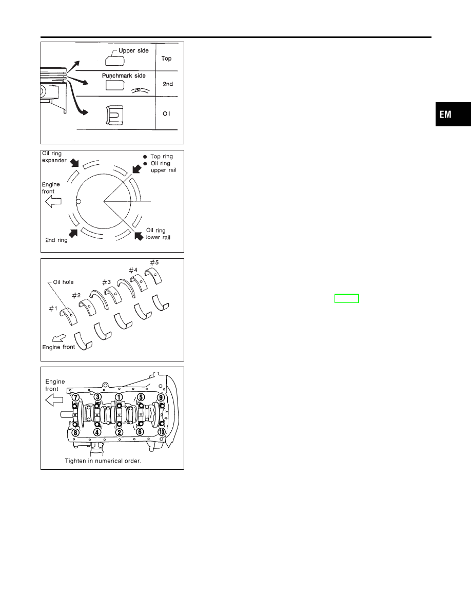
3.
Set piston rings as shown.
CAUTION:
I
When piston rings are not replaced, make sure that piston
rings are mounted in their original positions.
I
Install new piston rings either side up if there is no punch
mark.
SEM160B
I
Align piston rings so that end gaps are positioned as
shown.
SEM685D
CRANKSHAFT
NCEM0027S02
1.
Set main bearings in their proper positions on cylinder block
and main bearing cap.
I
Confirm that correct main bearings are selected by using
Method A or Method B. Refer to EM-60.
I
Apply new engine oil to bearing surfaces.
SEM069G
2.
Install crankshaft and main bearing caps, then tighten bolts to
the specified torque.
I
Prior to tightening bearing cap bolts, shift crankshaft back
and forth to properly seat the bearing cap.
I
Apply new engine oil to threads and seating surfaces of
bearing cap bolts before installing them.
I
Tightening procedure:
a.
Tighten all bolts to 7 to 12 N·m (0.7 to 1.3 kg-m, 61 to 112
ft-lb).
GI
MA
LC
EC
FE
CL
MT
AT
AX
SU
BR
ST
RS
BT
HA
SC
EL
IDX
CYLINDER BLOCK
Assembly (Cont’d)
EM-65