Infiniti G20 (P11). Manual - part 355
Trouble Diagnoses
NCEL0115
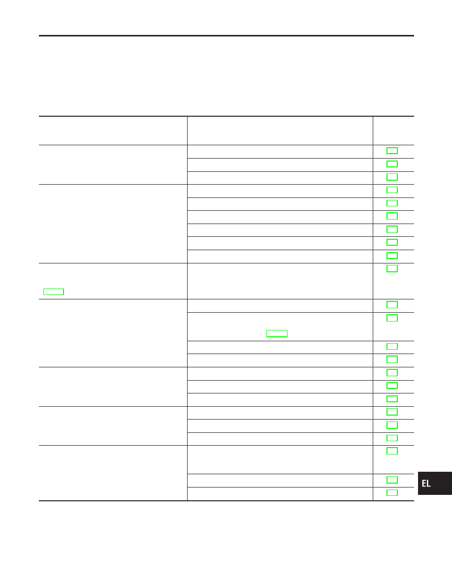
SYMPTOM CHART
NCEL0115S01
NOTE:
I
Always check remote controller battery before replacing
remote controller.
I
Trunk lid opener operation and panic alarm operation of multi-
remote control system does not activate with the ignition key
inserted in the ignition key cylinder.
Symptom
Diagnoses/service procedure
Reference
page
(EL-
)
All function of multi-remote control system do not
operate.
1. Remote controller battery check
2. Power supply and ground circuit for control unit check
3. Replace romote controller. Refer to ID Code Entry Procedure.
The new ID of remote controller cannot entered.
1. Remote controller battery check
2. Key switch (insert) check
3. Door switch check
4. Door lock/unlock switch check
5. Power supply and ground circuit for control unit check
6. Replace romote controller. Refer to ID Code Entry Procedure.
Door lock or unlock does not function.
(If the power door lock system does not operate
manually, check power door lock system. Refer to
EL-181.)
1. Replace remote controller. Refer to ID Code Entry Procedure.
Hazard and horn reminder do not activate prop-
erly when pressing lock or unlock button of
remote controller.
1. Harzard reminder check
2. Horn reminder check*
*: Horn chirp can be activated or deactivated. First check the
horn chirp setting. Refer to EL-191.
3. Door switch check
4. Replace remote controller. Refer to ID Code Entry Procedure.
Trunk lid does not open when trunk opener button
is pressed.
1. Trunk lid opener operation check
2. Key switch (insert) check
3. Replace remote controller. Refer to ID Code Entry Procedure.
Interior lamp does not turn on for 30 seconds
when pressing unlock button of remote controller.
1. Interior room lamp operation check
2. Door switch check
3. Door unlock sensor check
Panic alarm (horn and headlamp) does not acti-
vate when panic alarm button is continuously
pressed more than 1.5 seconds.
1. Vehicle security operation check. Refer to “PRELIMINALY
CHECK” in “VEHICLE SECURITY (THEFT WARNING) SYS-
TEM”.
2. Key switch (insert) check
3. Replace remote controller. Refer to ID Code Entry Procedure.
GI
MA
EM
LC
EC
FE
CL
MT
AT
AX
SU
BR
ST
RS
BT
HA
SC
IDX
MULTI-REMOTE CONTROL SYSTEM
Trouble Diagnoses
EL-197