Infiniti G20 (P11). Manual - part 353


  Index      Infiniti     Infiniti G20 (P11) - service repair manual 1999-2002 year


Search            


Content   ..  351  352  353  354   ..


Infiniti G20 (P11). Manual - part 353


2

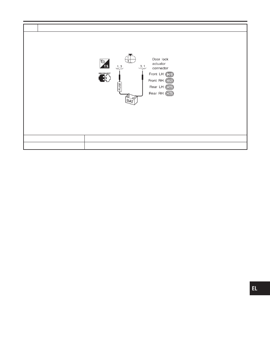
CHECK DOOR LOCK ACTUATOR

1. Disconnect door lock actuator connector.
2. Apply 12V direct current to door lock actuator and check operation.

I

Door lock actuator operation:

SEL736UC

Terminals between (+): 3 and (−): 1

Unlocked

Locked

Terminals between (+): 1 and (−): 3

Locked

Unlocked

OK or NG

OK

©

Check harness for open or short between control unit connector and door lock actuator.

NG

©

Replace door lock actuator.

GI

MA

EM

LC

EC

FE

CL

MT

AT

AX

SU

BR

ST

RS

BT

HA

SC

IDX

POWER DOOR LOCK

Trouble Diagnoses (Cont’d)

EL-189

Component Parts and Harness Connector
Location

NCEL0111

SEL188X

System Description

NCEL0112

INPUTS

NCEL0112S01

Power is supplied at all times

I

to key switch terminal 1

I

through 10A fuse [No. 24, located in the fuse block (J/B)].

When the key switch is ON (ignition key is inserted in key cylinder), power is supplied

I

through key switch terminal 2

I

to smart entrance control unit terminal 32.

When the front door switch (driver side) is OPEN, ground is supplied

I

to smart entrance control unit terminal 29

I

through front door switch (driver side) terminal 2

I

to front door switch (driver side) terminal 3

I

through body grounds B7 and B24.

When the front door switch (passenger side) is OPEN, ground is supplied

I

to smart entrance control unit terminal 40

I

through front door switch (passenger side) terminal 1

I

through the front door switch RH case ground.

When the rear door switch is OPEN, ground is supplied

I

to smart entrance control unit terminal 28

I

through each door switch case ground.

MULTI-REMOTE CONTROL SYSTEM

Component Parts and Harness Connector Location

EL-190

When door lock and unlock switch is LOCKED, ground is supplied

I

to smart entrance control unit terminal 23

I

through door lock and unlock switch terminals 8 and 6

I

through body grounds M15, M71 and M76.

When door lock and unlock switch is UNLOCKED, ground is supplied

I

to smart entrance control unit terminal 35

I

through door lock and unlock switch terminals 1 and 6

I

through body grounds M15, M71 and M76.

When the front door lock actuator (driver side) (door unlock sensor) is UNLOCKED, ground is supplied

I

to smart entrance control unit terminal 36

I

through door lock actuator (driver side) (door unlock sensor) terminal 4

I

to door lock actuator (driver side) (door unlock sensor) terminal 2

I

through body grounds M15, M71 and M76.

Remote controller signal is inputted to smart entrance control unit (the antenna of the system is combined with
smart entrance control unit).
Then smart entrance control unit supplies power and ground to each door lock actuator.
The multi-remote control system controls operation of the

I

power door lock

I

interior lamp

I

panic alarm

I

hazard and horn reminder

OPERATED PROCEDURE

NCEL0112S02

Power Door Lock Operation

NCEL0112S0201

Smart entrance control unit receives a LOCK signal from remote controller. Smart entrance control unit locks
all doors with input of LOCK signal from remote controller.
When an UNLOCK signal is sent from remote controller once, driver’s door will be unlocked.
Then, if an UNLOCK signal is sent from remote controller again within 5 seconds, all other door will be
unlocked.

Hazard and Horn Reminder

NCEL0112S0204

Power is supplied at all times

I

to multi-remote control relay terminals 1, 3 and 6

I

through 10A fuse [No. 20, located in the fuse block (J/B)],

I

to horn relay terminals 1 and 3

I

through 10A fuse (No. 36, located in the fusible link and fuse box) and

I

to horn relay terminal 6

I

through 10A fuse (No. 41, located in the fusible link and fuse box).

When smart entrance control unit receives LOCK or UNLOCK signal from remote controller with all doors
closed, ground is supplied

I

to multi-remote control relay terminal 2

I

through smart entrance control unit terminal 7, and

I

to horn relay terminal 2

I

through smart entrance control unit terminal 19

Multi-remote control relay and horn relay are now energized, and hazard warning lamp flashes and horn
sounds as a reminder.
The hazard and horn reminder has a horn chirp mode and a non-horn chirp mode.
Operating function of hazard and horn reminder

Horn chirp mode

Non-horn chirp mode

Hazard warning lamp

flash

Horn sound

Hazard warning lamp

flash

Horn sound

Lock

Twice

Once

Twice

GI

MA

EM

LC

EC

FE

CL

MT

AT

AX

SU

BR

ST

RS

BT

HA

SC

IDX

MULTI-REMOTE CONTROL SYSTEM

System Description (Cont’d)

EL-191

Horn chirp mode

Non-horn chirp mode

Hazard warning lamp

flash

Horn sound

Hazard warning lamp

flash

Horn sound

Unlock

Once

How to change hazard and horn reminder mode
When LOCK and UNLOCK signals are sent from the remote controller for more than 2 seconds at the same
time, the hazard and horn reminder mode is changed and hazard warning lamp flashes and horn sounds as
follows:

SEL153W

Trunk Lid Opener Operation

NCEL0112S0205

Power is supplied at all times

I

through 15A fuse [No. 15, located in the fuse block (J/B)]

I

to trunk lid opener relay terminals 1 and 5.

When a TRUNK OPEN signal is sent from multi-remote controller with key switch OFF, ground is supplied

I

to trunk lid opener relay terminal 2

I

through smart entrance control unit terminal 12.

Trunk opener relay is now energized and trunk lid opener actuator opens trunk lid.

Interior Lamp Operation

NCEL0112S0202

When the following input signals are both supplied:

I

driver’s door LOCKED:

I

door switch CLOSED (when all the doors are closed);

multi-remote control system turns on interior lamp (for 30 seconds) with input of UNLOCK signal from remote
controller.
For detailed description, refer to “SMART ENTRANCE CONTROL UNIT” (EL-242).

Panic Alarm Operation

NCEL0112S0203

When key switch is OFF (when ignition key is not inserted in key cylinder), multi-remote control system turns
on and off horn and headlamp intermittently with input of PANIC ALARM signal from remote controller.
For detailed description, refer to “VEHICLE SECURITY (THEFT WARNING) SYSTEM” (EL-215).

MULTI-REMOTE CONTROL SYSTEM

System Description (Cont’d)

EL-192


Content   ..  351  352  353  354   ..