Infiniti G20 (P11). Manual - part 344
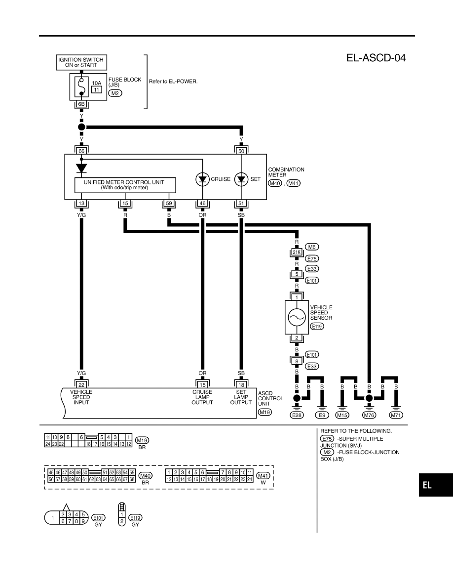
FIG. 4
NCEL0097S04
TEL856B
GI
MA
EM
LC
EC
FE
CL
MT
AT
AX
SU
BR
ST
RS
BT
HA
SC
IDX
AUTOMATIC SPEED CONTROL DEVICE (ASCD)
Wiring Diagram — ASCD — (Cont’d)
EL-153
|
|
|
FIG. 4 NCEL0097S04 TEL856B GI MA EM LC EC FE CL MT AT AX SU BR ST RS BT HA SC IDX AUTOMATIC SPEED CONTROL DEVICE (ASCD) Wiring Diagram — ASCD — (Cont’d) EL-153 |