Infiniti G20 (P11). Manual - part 342
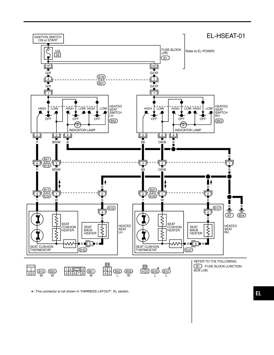
Wiring Diagram — HSEAT —
NCEL0093
TEL519B
GI
MA
EM
LC
EC
FE
CL
MT
AT
AX
SU
BR
ST
RS
BT
HA
SC
IDX
HEATED SEAT
Wiring Diagram — HSEAT —
EL-145
|
|
|
Wiring Diagram — HSEAT — NCEL0093 TEL519B GI MA EM LC EC FE CL MT AT AX SU BR ST RS BT HA SC IDX HEATED SEAT Wiring Diagram — HSEAT — EL-145 |