Infiniti G20 (P11). Manual - part 333


  Index      Infiniti     Infiniti G20 (P11) - service repair manual 1999-2002 year


Search            


Content   ..  331  332  333  334   ..


Infiniti G20 (P11). Manual - part 333


Trouble Diagnoses

NCEL0055

SYMPTOM CHART

NCEL0055S01

REFERENCE PAGE (EL-

)

109

110

111

112

113

SYMPTOM

POWER

SUPPL

Y

AND

GROUND

CIRCUIT

CHECK

LIGHTING

SWITCH

INPUT

SIGNAL

CHECK

KEY

SWITCH

(INSER

T)

CHECK

SEA

T

BEL

T

BUCKLE

SWITCH

CHECK

DRIVER

SIDE

DOOR

SWITCH

CHECK

Light warning chime does not acti-
vate.

X

X

X

Ignition key warning chime does not
activate.

X

X

X

Seat belt warning chime does not
activate.

X

X

All warning chimes do not activate.

X

X

SEL177XA

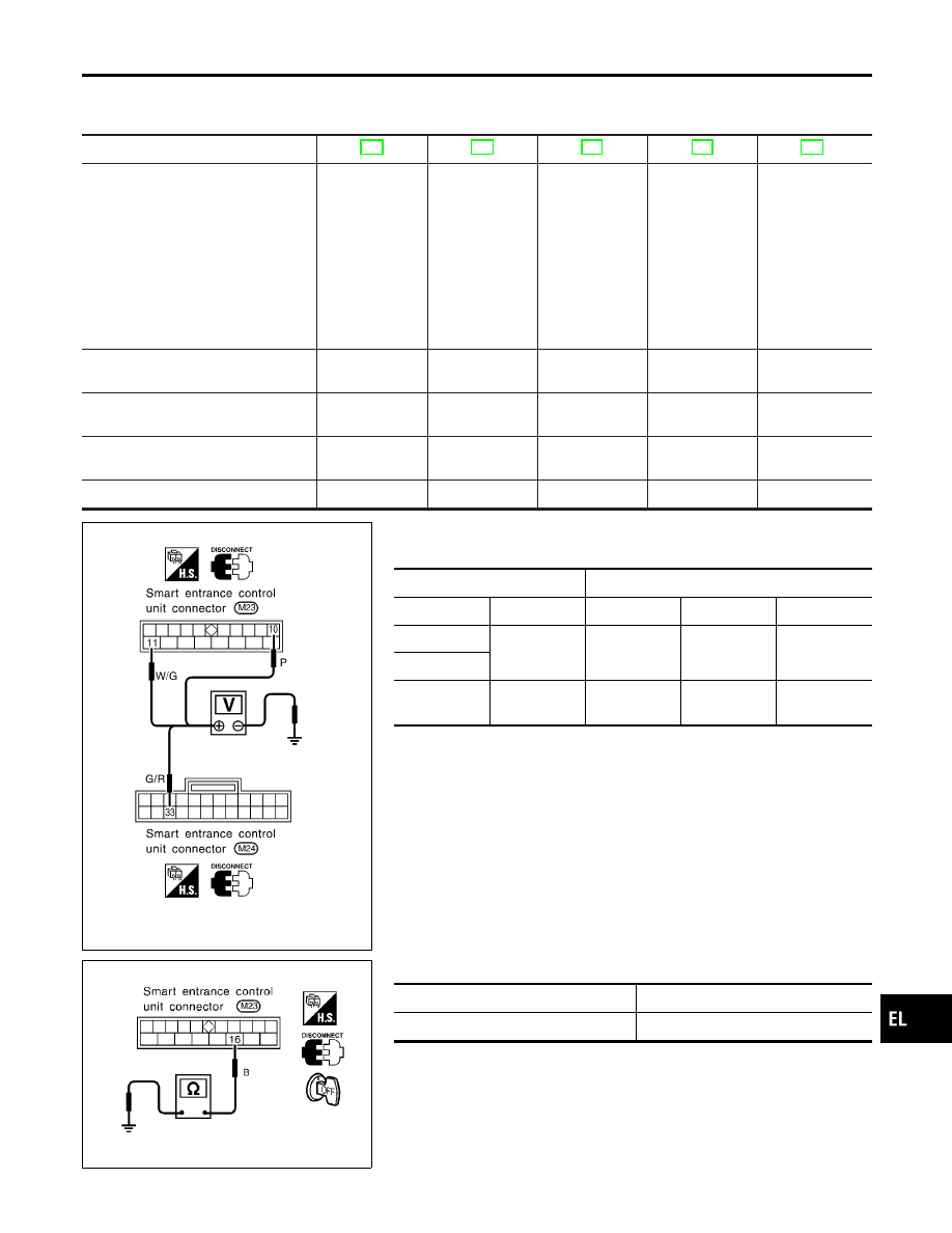
POWER SUPPLY AND GROUND CIRCUIT CHECK

NCEL0055S02

Power Supply Circuit Check

NCEL0055S0201

Terminals

Ignition switch position

(+)

(−)

OFF

ACC

ON

10

Ground

Battery
voltage

Battery
voltage

Battery
voltage

11

33

Ground

0V

0V

Battery
voltage

SEL781V

Ground Circuit Check

NCEL0055S0202

Terminals

Continuity

16 - Ground

Yes

GI

MA

EM

LC

EC

FE

CL

MT

AT

AX

SU

BR

ST

RS

BT

HA

SC

IDX

WARNING CHIME

Trouble Diagnoses

EL-109

LIGHTING SWITCH INPUT SIGNAL CHECK

=NCEL0055S03

1

CHECK LIGHTING SWITCH INPUT SIGNAL

Check voltage between control unit terminal 34 and ground.

SEL782V

Voltage [V]:

Condition of lighting switch: 1ST or 2ND

Approx. 12

Condition of lighting switch: OFF

0

OK or NG

OK

©

Lighting switch is OK.

NG

©

Check the following.

I

10A fuse (No. 34, located in the fuse and fusible link box)

I

Harness for open or short between control unit and lighting switch

WARNING CHIME

Trouble Diagnoses (Cont’d)

EL-110

KEY SWITCH (INSERT) CHECK

=NCEL0055S04

1

CHECK KEY SWITCH INPUT SIGNAL

Check voltage between control unit terminal 32 and ground.

SEL783V

Voltage [V]:

Condition of key switch: Key is inserted.

Approx. 12

Condition of key switch: Key is withdrawn.

0

OK or NG

OK

©

Key switch is OK.

NG

©

GO TO 2.

2

CHECK KEY SWITCH (INSERT)

Check continuity between terminals 1 and 2.

SEL784V

Continuity:

Condition of key switch: Key is inserted.

Yes

Condition of key switch: Key is removed.

No

OK or NG

OK

©

Check the following.

I

10A fuse [No. 24, located in fuse block (J/B)]

I

Harness for open or short between key switch and fuse

I

Harness for open or short between control unit and key switch

NG

©

Replace key switch.

GI

MA

EM

LC

EC

FE

CL

MT

AT

AX

SU

BR

ST

RS

BT

HA

SC

IDX

WARNING CHIME

Trouble Diagnoses (Cont’d)

EL-111

SEAT BELT BUCKLE SWITCH CHECK

=NCEL0055S05

1

CHECK SEAT BELT BUCKLE SWITCH INPUT SIGNAL

1. Turn ignition switch “ON”.
2. Check voltage between control unit terminal 22 and ground.

SEL785V

Voltage [V]:

Condition of seat belt buckle switch: Fastened

Approx. 12

Condition of seat belt buckle switch: Unfastened

0

OK or NG

OK

©

Seat belt buckle switch is OK.

NG

©

GO TO 2.

2

CHECK SEAT BELT BUCKLE SWITCH

Check continuity between terminals 1 and 2 when seat belt is fastened and unfastened.

SEL298VB

Continuity:

Seat belt is fastened.

No

Seat belt is unfastened.

Yes

OK or NG

OK

©

Check the following.

I

Seat belt buckle switch ground circuit

I

Harness for open or short between control unit and seat belt buckle switch

NG

©

Replace seat belt buckle switch.

WARNING CHIME

Trouble Diagnoses (Cont’d)

EL-112


Content   ..  331  332  333  334   ..