Infiniti G20 (P11). Manual - part 239


  Index      Infiniti     Infiniti G20 (P11) - service repair manual 1999-2002 year


Search            


Content   ..  237  238  239  240   ..


Infiniti G20 (P11). Manual - part 239


6

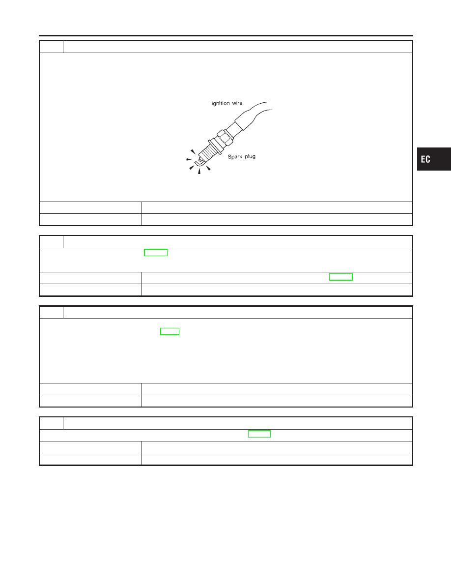
CHECK IGNITION SPARK

1. Disconnect ignition wire from spark plug.
2. Connect a known good spark plug to the ignition wire.
3. Place end of spark plug against a suitable ground and crank engine.
4. Check for spark.

SEF282G

OK or NG

OK

©

GO TO 8.

NG

©

GO TO 7.

7

CHECK IGNITION WIRES

Refer to “Component Inspection”, EC-328.

OK or NG

OK

©

Check ignition coil, power transistor and their circuits. Refer to EC-590.

NG

©

Replace.

8

CHECK INJECTOR

1. Turn ignition switch “OFF”.
2. Remove injector assembly. Refer to EC-51.

Keep fuel hose and all injectors connected to injector gallery.

3. Disconnect distributor harness connector.
4. Turn ignition switch “ON”.

Make sure fuel does not drip from injector.

OK or NG

OK (Does not drip)

©

GO TO 9.

NG (Drips)

©

Replace the injector(s) from which fuel is dripping.

9

CHECK INTERMITTENT INCIDENT

Perform “TROUBLE DIAGNOSIS FOR INTERMITTENT INCIDENT”, EC-146.

Trouble is fixed

©

INSPECTION END

Trouble is not fixed

©

Replace three way catalyst.

GI

MA

EM

LC

FE

CL

MT

AT

AX

SU

BR

ST

RS

BT

HA

SC

EL

IDX

DTC P0420 THREE WAY CATALYST FUNCTION

Diagnostic Procedure (Cont’d)

EC-367

On Board Diagnosis Logic

NCEC0527

NOTE:
If DTC P0440 is displayed with P1448, perform trouble diagno-
sis for DTC P1448 first. (See EC-549.)
This diagnosis detects leaks in the EVAP purge line using engine
intake manifold vacuum.
If pressure does not increase, the ECM will check for leaks in the
line between the fuel tank and EVAP canister purge volume con-
trol solenoid valve, under the following “Vacuum test” conditions.
The vacuum cut valve bypass valve is opened to clear the line
between the fuel tank and the EVAP canister purge volume control
solenoid valve. The EVAP canister vent control valve will then be
closed to shut the EVAP purge line off. The EVAP canister purge
volume control solenoid valve is opened to depressurize the EVAP
purge line using intake manifold vacuum. After this occurs, the
EVAP canister purge volume control solenoid valve will be closed.

SEF323U

Malfunction is detected when EVAP control system has a leak,
EVAP control system does not operate properly.

CAUTION:

I

Use only a genuine NISSAN fuel filler cap as a replace-
ment. If an incorrect fuel filler cap is used, the MIL may
come on.

I

If the fuel filler cap is not tightened properly, the MIL may
come on.

I

Use only a genuine NISSAN rubber tube as a replacement.

Possible Cause

NCEC0528

I

Incorrect fuel tank vacuum relief valve

I

Incorrect fuel filler cap used

I

Fuel filler cap remains open or fails to close.

I

Foreign matter caught in fuel filler cap.

I

Leak is in line between intake manifold and EVAP canister
purge volume control solenoid valve.

I

Foreign matter caught in EVAP canister vent control valve.

I

EVAP canister or fuel tank leaks

I

EVAP purge line (pipe and rubber tube) leaks

DTC P0440 EVAP CONTROL SYSTEM (SMALL LEAK) (NEGATIVE PRESSURE)

On Board Diagnosis Logic

EC-368

I

EVAP purge line rubber tube bent.

I

Blocked or bent rubber tube to EVAP control system pressure
sensor

I

Loose or disconnected rubber tube

I

EVAP canister vent control valve and the circuit

I

EVAP canister purge volume control solenoid valve and the
circuit

I

Fuel tank temperature sensor

I

O-ring of EVAP canister vent control valve is missing or dam-
aged.

I

Water separator

I

EVAP canister is saturated with water.

I

EVAP control system pressure sensor

I

Fuel level sensor and the circuit

I

Refueling control valve

I

ORVR system leaks

SEF565X

SEF566X

SEF567X

DTC Confirmation Procedure

NCEC0529

CAUTION:

Never remove fuel filler cap during the DTC confirmation pro-
cedure.
NOTE:

I

If DTC P0440 or P1440 is displayed with P1448, perform
trouble diagnosis for DTC P1448 first. (See EC-549.)

I

Make sure that EVAP hoses are connected to EVAP canis-
ter purge volume control solenoid valve properly.

I

If

“DTC

Confirmation

Procedure”

has

been

previously

conducted, always turn ignition switch “OFF” and wait at least
10 seconds before conducting the next test.

TESTING CONDITION:

I

Perform “DTC WORK SUPPORT” when the fuel level is
between 1/4 to 3/4 full and vehicle is placed on flat level
surface.

I

Always perform test at a temperature of 0 to 30°C (32 to
86°F).

WITH CONSULT-II

NCEC0529S01

1)

Turn ignition switch “ON”.

2)

Turn ignition switch “OFF” and wait at least 10 seconds.

3)

Turn ignition switch “ON” and select “DATA MONITOR” mode
with CONSULT-II.

4)

Make sure that the following conditions are met.
COOLAN TEMP/S: 0 - 70°C (32 - 158°F)
INT/A TEMP SE: 0 - 30°C (32 - 86°F)

5)

Select “EVAP SML LEAK P0440/P1440” of “EVAPORATIVE
SYSTEM” in “DTC WORK SUPPORT” mode with CONSULT-
II.
Follow the instruction displayed.

GI

MA

EM

LC

FE

CL

MT

AT

AX

SU

BR

ST

RS

BT

HA

SC

EL

IDX

DTC P0440 EVAP CONTROL SYSTEM (SMALL LEAK) (NEGATIVE PRESSURE)

Possible Cause (Cont’d)

EC-369

NOTE:
If the engine speed cannot be maintained within the range dis-
played on the CONSULT-II screen, go to “Basic Inspection”,
EC-107.
6)

Make sure that “OK” is displayed.
If “NG” is displayed, refer to “Diagnostic Procedure”, EC-370.

WITH GST

NCEC0529S02

NOTE:
Be sure to read the explanation of “Driving Pattern” on EC-74
before driving vehicle.
1)

Start engine.

2)

Drive vehicle according to “Driving Pattern”, EC-74.

3)

Stop vehicle.

4)

Select “MODE 1” with GST.

I

If SRT of EVAP system is not set yet, go to the following step.

I

If SRT of EVAP system is set, the result will be OK.

5)

Turn ignition switch “OFF” and wait at least 10 seconds.

6)

Start engine.
It is not necessary to cool engine down before driving.

7)

Drive vehicle again according to the “Driving Pattern”, EC-74.

8)

Stop vehicle.

9)

Select “MODE 3” with GST.

I

If P0440 or P1440 is displayed on the screen, go to “Diagnos-
tic Procedure”, EC-370.

I

If P1447 is displayed on the screen, go to “Diagnostic Proce-
dure” for DTC P1447, EC-540.

I

If P0440, P1440 and P1447 are not displayed on the screen,
go to the following step.

10) Select “MODE 1” with GST.

I

If SRT of EVAP system is set, the result will be OK.

I

If SRT of EVAP system is not set, go to step 6.

Diagnostic Procedure

NCEC0530

1

CHECK FUEL FILLER CAP DESIGN

1. Turn ignition switch “OFF”.
2. Check for genuine NISSAN fuel filler cap design.

SEF915U

OK or NG

OK

©

GO TO 2.

NG

©

Replace with genuine NISSAN fuel filler cap.

DTC P0440 EVAP CONTROL SYSTEM (SMALL LEAK) (NEGATIVE PRESSURE)

DTC Confirmation Procedure (Cont’d)

EC-370


Content   ..  237  238  239  240   ..