Infiniti G20 (P11). Manual - part 216


  Index      Infiniti     Infiniti G20 (P11) - service repair manual 1999-2002 year


Search            


Content   ..  214  215  216  217   ..


Infiniti G20 (P11). Manual - part 216


Diagnostic Procedure

NCEC0191

1

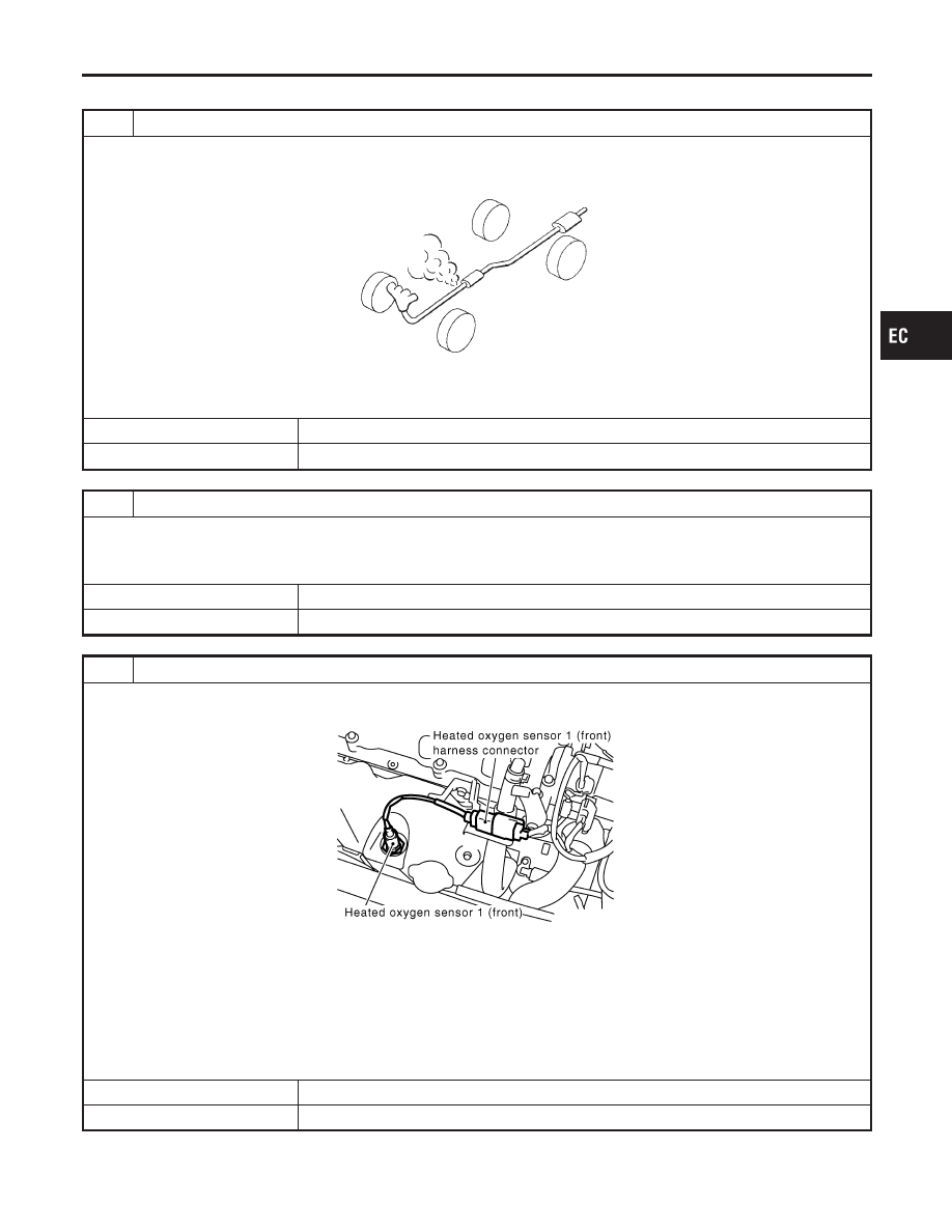
CHECK EXHAUST AIR LEAK

1. Start engine and run it at idle.
2. Listen for an exhaust air leak before three way catalyst.

SEF099P

OK or NG

OK

©

GO TO 2.

NG

©

Repair or replace.

2

CHECK FOR INTAKE AIR LEAK AND PCV HOSE

1. Listen for an intake air leak after the mass air flow sensor.
2. Check PCV hose connection.

OK or NG

OK

©

GO TO 3.

NG

©

Repair or replace.

3

CHECK HEATED OXYGEN SENSOR 1 (FRONT) CIRCUIT

1. Turn ignition switch “OFF”.
2. Disconnect heated oxygen sensor 1 (front) harness connector and ECM harness connector.

SEF917Z

3. Check harness continuity between ECM terminal 62 and HO2S1 terminal 2.

Refer to Wiring Diagram.

Continuity should exist.

4. Check harness continuity between ECM terminal 62 (or HO2S1 terminal 2) and ground.

Refer to Wiring Diagram.

Continuity should not exist.

5. Also check harness for short to ground and short to power.

OK or NG

OK

©

GO TO 4.

NG

©

Repair open circuit or short to ground or short to power in harness or connectors.

GI

MA

EM

LC

FE

CL

MT

AT

AX

SU

BR

ST

RS

BT

HA

SC

EL

IDX

DTC P0171 FUEL INJECTION SYSTEM FUNCTION (LEAN SIDE)

Diagnostic Procedure

EC-275

4

CHECK FUEL PRESSURE

1. Release fuel pressure to zero.

Refer to EC-50.

2. Install fuel pressure gauge and check fuel pressure.

At idling:

When fuel pressure regulator valve vacuum hose is connected.

235 kPa (2.4 kg/cm

2

, 34 psi)

When fuel pressure regulator valve vacuum hose is disconnected.

294 kPa (3.0 kg/cm

2

, 43 psi)

OK or NG

OK

©

GO TO 6.

NG

©

GO TO 5.

5

DETECT MALFUNCTIONING PART

Check the following.

I

Fuel pump and circuit (Refer to EC-605.)

I

Fuel pressure regulator (Refer to EC-51.)

I

Fuel lines. Refer to MA-16, “Checking Fuel Lines”.

I

Fuel filter for clogging

©

Repair or replace.

6

CHECK MASS AIR FLOW SENSOR

With CONSULT-II

1. Install all removed parts.
2. Check “MASS AIR FLOW” in “DATA MONITOR” mode with CONSULT-II.

at idling: 2.5 - 5.0 g·m/sec
at 2,500 rpm: 7.1 - 12.5 g·m/sec

With GST

1. Install all removed parts.
2. Check mass air flow sensor signal in MODE 1 with GST.

at idling: 2.5 - 5.0 g·m/sec
at 2,500 rpm: 7.1 - 12.5 g·m/sec

OK or NG

OK

©

GO TO 7.

NG

©

Check connectors for rusted terminals or loose connections in the mass air flow sensor
circuit or engine grounds. Refer to EC-154.

DTC P0171 FUEL INJECTION SYSTEM FUNCTION (LEAN SIDE)

Diagnostic Procedure (Cont’d)

EC-276

7

CHECK FUNCTION OF INJECTORS

With CONSULT-II

1. Start engine.
2. Perform “POWER BALANCE” in “ACTIVE TEST” mode with CONSULT-II.

SEF190Y

3. Make sure that each circuit produces a momentary engine speed drop.

Without CONSULT-II

1. Start engine.
2. Listen to each injector operating sound.

MEC703B

Clicking noise should be heard.

OK or NG

OK

©

GO TO 8.

NG

©

Perform trouble diagnosis for “INJECTORS”, EC-596.

8

REMOVE INJECTOR

1. Confirm that the engine is cooled down and there are no fire hazards near the vehicle.
2. Turn ignition switch “OFF”.
3. Remove injector with fuel tube assembly. Refer to EC-51.

Keep fuel hose and all injectors connected to injector gallery. The injector harness connectors should remain con-
nected.

©

GO TO 9.

GI

MA

EM

LC

FE

CL

MT

AT

AX

SU

BR

ST

RS

BT

HA

SC

EL

IDX

DTC P0171 FUEL INJECTION SYSTEM FUNCTION (LEAN SIDE)

Diagnostic Procedure (Cont’d)

EC-277

9

CHECK INJECTOR

1. Disconnect all ignition wires.
2. Place pans or saucers under each injector.
3. Crank engine for about 3 seconds. Make sure that fuel sprays out from injectors.

SEF595Q

Fuel should be sprayed evenly for each cylinder.

OK or NG

OK

©

GO TO 10.

NG

©

Replace injectors from which fuel does not spray out. Always replace O-ring with new
one.

10

CHECK INTERMITTENT INCIDENT

Perform “TROUBLE DIAGNOSIS FOR INTERMITTENT INCIDENT”, EC-146.

©

INSPECTION END

DTC P0171 FUEL INJECTION SYSTEM FUNCTION (LEAN SIDE)

Diagnostic Procedure (Cont’d)

EC-278


Content   ..  214  215  216  217   ..