Infiniti G20 (P11). Manual - part 204


  Index      Infiniti     Infiniti G20 (P11) - service repair manual 1999-2002 year


Search            


Content   ..  202  203  204  205   ..


Infiniti G20 (P11). Manual - part 204


SEF301UA

On Board Diagnosis Logic

NCEC0131

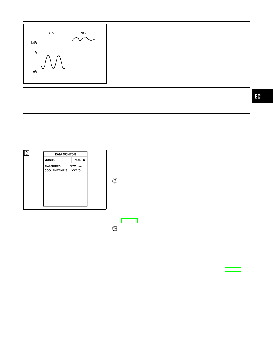
To judge the malfunction, the diagnosis checks that the heated
oxygen sensor 1 (front) output is not inordinately high.

DTC No.

Malfunction is detected when ...

Check Items (Possible Cause)

P0134

I

An excessively high voltage from the sensor is sent to
ECM.

I

Harness or connectors
(The sensor circuit is open or shorted.)

I

Heated oxygen sensor 1 (front)

SEF174Y

DTC Confirmation Procedure

NCEC0132

NOTE:
If “DTC Confirmation Procedure” has been previously conducted,
always turn ignition switch “OFF” and wait at least 10 seconds
before conducting the next test.

With CONSULT-II

1)

Start engine and warm it up to normal operating temperature.

2)

Turn ignition switch “OFF” and wait at least 10 seconds.

3)

Turn ignition switch “ON”.

4)

Select “DATA MONITOR” mode with CONSULT-II.

5)

Restart engine and let it idle for 2 minutes.

6)

If 1st trip DTC is detected, go to “Diagnostic Procedure”,
EC-229.

With GST

1)

Start engine and warm it up to normal operating temperature.

2)

Turn ignition switch “OFF” and wait at least 10 seconds.

3)

Restart engine and let it idle for 2 minutes.

4)

Turn ignition switch “OFF” and wait at least 10 seconds.

5)

Restart engine and let it idle for 2 minutes.

6)

Select “MODE 3” with GST.

7)

If DTC is detected, go to “Diagnostic Procedure”, EC-229.

I

When using GST, “DTC Confirmation Procedure” should
be performed twice as much as when using CONSULT-II
because GST cannot display MODE 7 (1st trip DTC) con-
cerning this diagnosis. Therefore, using CONSULT-II is
recommended.

GI

MA

EM

LC

FE

CL

MT

AT

AX

SU

BR

ST

RS

BT

HA

SC

EL

IDX

DTC P0134 HEATED OXYGEN SENSOR 1 (FRONT) (HIGH VOLTAGE)

On Board Diagnosis Logic

EC-227

Wiring Diagram

NCEC0133

TEC837

DTC P0134 HEATED OXYGEN SENSOR 1 (FRONT) (HIGH VOLTAGE)

Wiring Diagram

EC-228

Diagnostic Procedure

NCEC0134

1

RETIGHTEN HEATED OXYGEN SENSOR 1 (FRONT)

Loosen and retighten heated oxygen sensor 1 (front).

Tightening torque:

40 - 60 N·m (4.1 - 6.1 kg-m, 30 - 44 ft-lb)

©

GO TO 2.

2

CHECK INPUT SIGNAL CIRCUIT

1. Disconnect heated oxygen sensor 1 (front) harness connector and ECM harness connector.

SEF917Z

2. Check harness continuity between ECM terminal 62 and HO2S1 terminal 2.

Refer to Wiring Diagram.

Continuity should exist.

3. Check harness continuity between ECM terminal 62 (or HO2S1 terminal 2) and ground.

Refer to Wiring Diagram.

Continuity should not exist.

4. Also check harness for short to power.

OK or NG

OK

©

GO TO 3.

NG

©

Repair open circuit or short to ground or short to power in harness or connectors.

3

CHECK HARNESS CONNECTOR

Check heated oxygen sensor 1 (front) harness connector for water.

Water should not exist.

OK or NG

OK

©

GO TO 4.

NG

©

Repair or replace harness connector.

4

CHECK HEATED OXYGEN SENSOR 1 (FRONT)

Refer to “Component Inspection”, EC-230.

OK or NG

OK

©

GO TO 5.

NG

©

Replace heated oxygen sensor 1 (front).

GI

MA

EM

LC

FE

CL

MT

AT

AX

SU

BR

ST

RS

BT

HA

SC

EL

IDX

DTC P0134 HEATED OXYGEN SENSOR 1 (FRONT) (HIGH VOLTAGE)

Diagnostic Procedure

EC-229

5

CHECK SHIELD CIRCUIT

1. Turn ignition switch “OFF”.
2. Disconnect joint connector-1.
3. Check the following.

I

Continuity between joint connector-1 terminal 2 and ground
Refer to Wiring Diagram.

I

Joint connector-1
(Refer to EL-274, “HARNESS LAYOUT”.)

Continuity should exist.

4. Also check harness for short to power. Then reconnect joint connector.

OK or NG

OK

©

GO TO 6.

NG

©

Repair open circuit or short to power in harness or connectors.

6

CHECK INTERMITTENT INCIDENT

Perform “TROUBLE DIAGNOSIS FOR INTERMITTENT INCIDENT”, EC-146.

©

INSPECTION END

SEF646Y

SEF217YA

Component Inspection

NCEC0135

HEATED OXYGEN SENSOR 1 (FRONT)

NCEC0135S01

With CONSULT-II

1)

Start engine and warm it up to normal operating temperature.

2)

Select “MANU TRIG” in “DATA MONITOR” mode, and select
“HO2S1 (B1)” and “HO2S1 MNTR (B1)”.

3)

Hold engine speed at 2,000 rpm under no load during the fol-
lowing steps.

4)

Touch “RECORD” on CONSULT-II screen.

5)

Check the following.

I

“HO2S1 MNTR (B1)” in “DATA MONITOR” mode changes from
“RICH” to “LEAN” to “RICH” five times in 10 seconds.
5 times (cycles) are counted as shown below:
R = “HO2S1 MNTR (B1)”, “RICH”
L = “HO2S1 MNTR (B1)”, “LEAN”

I

“HO2S1 (B1)” voltage goes above 0.6V at least once.

I

“HO2S1 (B1)” voltage goes below 0.3V at least once.

I

“HO2S1 (B1)” voltage never exceeds 1.0V.

CAUTION:

I

Discard any heated oxygen sensor which has been
dropped from a height of more than 0.5 m (19.7 in) onto a
hard surface such as a concrete floor; use a new one.

I

Before installing new oxygen sensor, clean exhaust sys-
tem threads using Oxygen Sensor Thread Cleaner tool
J-43897-18 or J-43897-12 and approved anti-seize lubri-
cant.

DTC P0134 HEATED OXYGEN SENSOR 1 (FRONT) (HIGH VOLTAGE)

Diagnostic Procedure (Cont’d)

EC-230


Content   ..  202  203  204  205   ..