Infiniti G20 (P11). Manual - part 182
TERMI-
NAL
NO.
WIRE
COLOR
ITEM
CONDITION
DATA (DC Voltage)
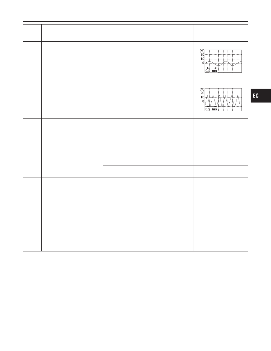
65
W
Crankshaft position
sensor (OBD)
[Engine is running]
I
Warm-up condition
I
Idle speed
3 - 5V (AC range)
SEF721W
[Engine is running]
I
Engine speed is 2,000 rpm
6 - 9V (AC range)
SEF722W
67
W/L
Power supply for ECM
(Back-up)
[Ignition switch “OFF”]
BATTERY VOLTAGE
(11 - 14V)
70
BR/Y
Engine coolant tem-
perature sensor
[Engine is running]
Approximately 0 - 4.8V
Output voltage varies with
engine coolant temperature.
71
GY
Throttle position sensor
signal output
[Engine is running]
I
Warm-up condition
I
Accelerator pedal fully released
Approximately 0.4V
[Ignition switch “ON”]
I
Accelerator pedal fully depressed
Approximately 4V
72
R/B
EGR temperature sen-
sor
[Engine is running]
I
Warm-up condition
I
Idle speed
Less than 4.5V
[Engine is running]
I
Warm-up condition
I
EGR system is operating
0 - 1.5V
73
G
Mass air flow sensor
ground
[Engine is running]
I
Warm-up condition
I
Idle speed
Approximately 0V
74
R/L
Refrigerant pressure
sensor
[Engine is running]
I
Warm-up condition
I
Both A/C switch and blower switch are “ON”
(Compressor operates)
0.36 - 3.88V
GI
MA
EM
LC
FE
CL
MT
AT
AX
SU
BR
ST
RS
BT
HA
SC
EL
IDX
TROUBLE DIAGNOSIS — GENERAL DESCRIPTION
ECM Terminals and Reference Value (Cont’d)
EC-139