Infiniti G20 (P11). Manual - part 159


  Index      Infiniti     Infiniti G20 (P11) - service repair manual 1999-2002 year


Search            


Content   ..  157  158  159  160   ..


Infiniti G20 (P11). Manual - part 159


10

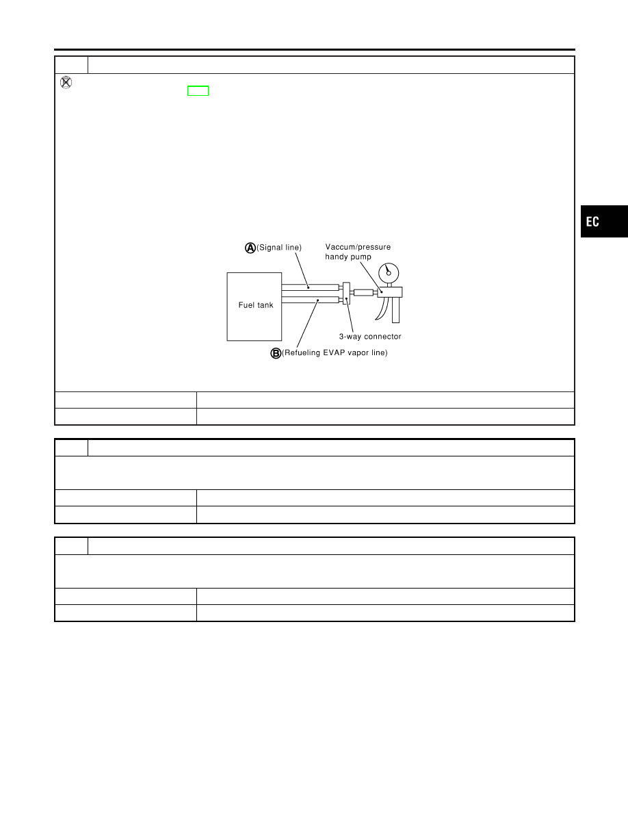
CHECK REFUELING EVAP VAPOR CUT VALVE

Without CONSULT-II

1. Remove fuel tank. Refer to FE-5, “FUEL SYSTEM”.
2. Drain fuel from the tank as follows:
a. Remove fuel level sensor unit retainer.
b. Drain fuel from the tank using a hand pump into a fuel container.
3. Check refueling EVAP vapor cut valve for being stuck to close as follows.

Blow air into the refueling EVAP vapor cut valve (from hose end B), and check that the air flows freely into the tank.

4. Check EVAP vapor cut valve for being stuck to open as follows.
a. Connect vacuum pump to hose ends A and B using a suitable 3-way connector.
b. Remove fuel level sensor unit retainer with fuel level sensor unit.

Always replace O-ring with new one.

c. Put fuel tank upside down.
d. Apply vacuum pressure to both hose ends A and B [−13.3 kPa (−100 mmHg, −3.94 inHg)] with fuel level sensor unit

retainer remaining open and check that the pressure is applicable.

SEF968X

OK or NG

OK

©

GO TO 11.

NG

©

Replace refueling EVAP vapor cut valve with fuel tank.

11

CHECK FUEL FILLER TUBE

Check filler neck tube and hose connected to the fuel tank for clogging, dents and cracks.

OK or NG

OK

©

GO TO 12.

NG

©

Replace fuel filler tube.

12

CHECK ONE-WAY FUEL VALVE-I

Check one-way valve for clogging.

OK or NG

OK

©

GO TO 13.

NG

©

Repair or replace one-way fuel valve with fuel tank.

GI

MA

EM

LC

FE

CL

MT

AT

AX

SU

BR

ST

RS

BT

HA

SC

EL

IDX

ENGINE AND EMISSION BASIC CONTROL SYSTEM DESCRIPTION

On Board Refueling Vapor Recovery (ORVR) (Cont’d)

EC-47

13

CHECK ONE-WAY FUEL VALVE-II

1. Make sure that fuel is drained from the tank.
2. Remove fuel filler tube and hose.
3. Check one-way fuel valve for operation as follows.

When a stick is inserted, the valve should open, when removing stick it should close.

SEF665U

Do not drop any material into the tank.

OK or NG

OK

©

INSPECTION END

NG

©

Replace fuel filler tube or replace one-way fuel valve with fuel tank.

Positive Crankcase Ventilation

DESCRIPTION

NCEC0022

SEF833X

This system returns blow-by gas to the intake collector.
The positive crankcase ventilation (PCV) valve is provided to conduct crankcase blow-by gas to the intake
manifold.
During partial throttle operation of the engine, the intake manifold sucks the blow-by gas through the PCV
valve.
Normally, the capacity of the valve is sufficient to handle any blow-by and a small amount of ventilating air.
The ventilating air is then drawn from the air duct into the crankcase. In this process the air passes through
the hose connecting air inlet tubes to rocker cover.
Under full-throttle condition, the manifold vacuum is insufficient to draw the blow-by flow through the valve.
The flow goes through the hose connection in the reverse direction.
On vehicles with an excessively high blow-by, the valve does not meet the requirement. This is because some
of the flow will go through the hose connection to the intake collector under all conditions.

ENGINE AND EMISSION BASIC CONTROL SYSTEM DESCRIPTION

On Board Refueling Vapor Recovery (ORVR) (Cont’d)

EC-48

SEC137A

INSPECTION

NCEC0023

PCV (Positive Crankcase Ventilation) Valve

NCEC0023S01

With engine running at idle, remove PCV valve from rocker cover.
A properly working valve makes a hissing noise as air passes
through it. A strong vacuum should be felt immediately when a fin-
ger is placed over the valve inlet.

ET277

Ventilation Hose

NCEC0023S02

1.

Check hoses and hose connections for leaks.

2.

Disconnect all hoses and clean with compressed air. If any
hose cannot be freed of obstructions, replace.

GI

MA

EM

LC

FE

CL

MT

AT

AX

SU

BR

ST

RS

BT

HA

SC

EL

IDX

ENGINE AND EMISSION BASIC CONTROL SYSTEM DESCRIPTION

Positive Crankcase Ventilation (Cont’d)

EC-49

SAT845J

SEF214Y

Fuel Pressure Release

NCEC0024

Before disconnecting fuel line, release fuel pressure from fuel
line to eliminate danger.

WITH CONSULT-II

NCEC0024S01

1.

Start engine.

2.

Perform “FUEL PRESSURE RELEASE” in “WORK SUP-
PORT” mode with CONSULT-II.

3.

After engine stalls, crank it two or three times to release all fuel
pressure.

4.

Turn ignition switch OFF.

SEF834X

WITHOUT CONSULT-II

NCEC0024S02

1.

Remove fuse for fuel pump.

2.

Start engine.

3.

After engine stalls, crank it two or three times to release all fuel
pressure.

4.

Turn ignition switch OFF and reconnect fuel pump fuse.

SEF826X

Fuel Pressure Check

NCEC0025

I

When reconnecting fuel line, always use new clamps.

I

Make sure that clamp screw does not contact adjacent
parts.

I

Use a torque driver to tighten clamps.

I

Use Pressure Gauge to check fuel pressure.

I

Do not perform fuel pressure check with system operat-
ing. Fuel pressure gauge may indicate false readings.

1.

Release fuel pressure to zero.

2.

Disconnect fuel hose from fuel feed tube (engine side).

3.

Install pressure gauge between fuel hose and fuel feed tube.

4.

Start engine and check for fuel leakage.

5.

Read the indication of fuel pressure gauge.

At idle speed:

With vacuum hose connected

Approximately 235 kPa (2.4 kg/cm

2

, 34 psi)

With vacuum hose disconnected

Approximately 294 kPa (3.0 kg/cm

2

, 43 psi)

If results are unsatisfactory, perform Fuel Pressure Regulator
Check, EC-51.

BASIC SERVICE PROCEDURE

Fuel Pressure Release

EC-50


Content   ..  157  158  159  160   ..