Infiniti G20 (P11). Manual - part 94
SAT438D
2.
Install output shaft thrust needle bearing on bearing retainer.
SAT439D
3.
Install output shaft on transmission case.
SAT874DA
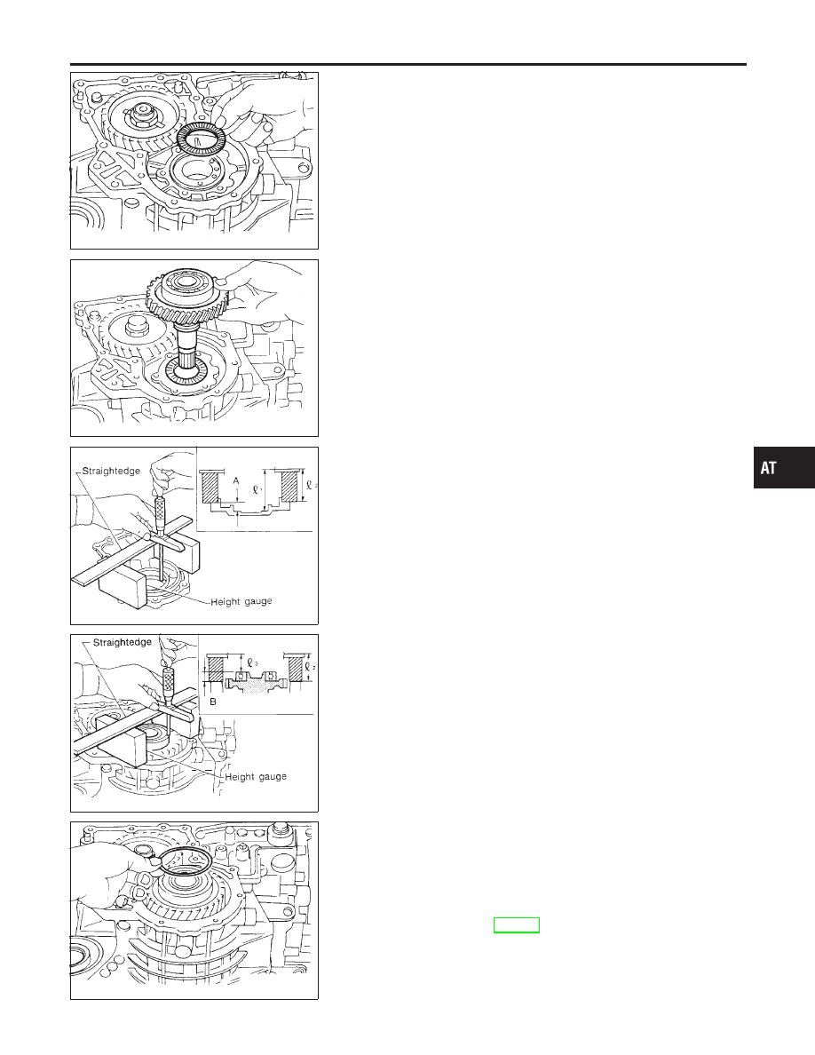
4.
Measure dimensions “
1
” and “
2
” at side cover and then cal-
culate dimension “A”.
I
Measure dimension “
1
” and “
2
” in at least two places
“A”: Distance between transmission case fitting surface
and adjusting shim mating surface
A =
1
−
2
2
: Height of gauge
SAT875DA
5.
Measure dimensions “
2
” and “
3
” and then calculate dimen-
sion “B”.
Measure “
2
” and “
3
” in at least two places.
“B”: Distance between the end of output shaft bearing
outer race and the side cover fitting surface of transmis-
sion case
B =
2
−
3
2
: Height of gauge
SAT440D
6.
Select proper thickness of adjusting shim so that output shaft
end play (clearance between side cover and output shaft bear-
ing) is within specifications.
Output shaft end play (A − B):
0 - 0.5 mm (0 - 0.020 in)
Output shaft end play adjusting shim:
Refer to SDS, AT-398.
7.
Install adjusting shim on output shaft bearing.
GI
MA
EM
LC
EC
FE
CL
MT
AX
SU
BR
ST
RS
BT
HA
SC
EL
IDX
ASSEMBLY
Adjustment (1) (Cont’d)
AT-373