Infiniti G20 (P11). Manual - part 84


  Index      Infiniti     Infiniti G20 (P11) - service repair manual 1999-2002 year


Search            


Content   ..  82  83  84  85   ..


Infiniti G20 (P11). Manual - part 84


INSPECTION

NCAT0147

Reverse Clutch Snap Ring, Spring Retainer and Return
Springs

NCAT0147S01

I

Check for deformation, fatigue or damage.

I

Replace if necessary.

I

When replacing spring retainer and return springs,
replace them as a set.

SAT162D

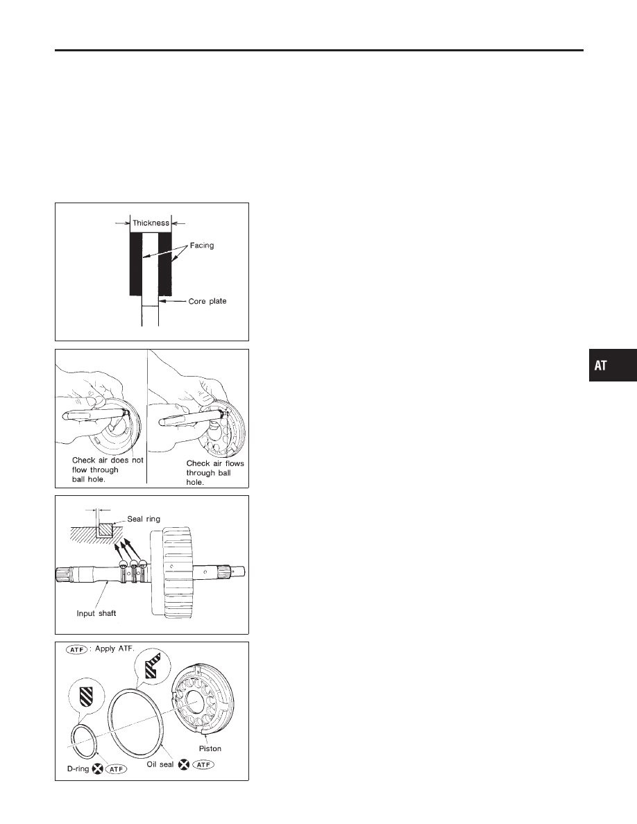
High Clutch Drive Plates

NCAT0147S02

I

Check facing for burns, cracks or damage.

I

Measure thickness of facing.

Thickness of drive plate:

Standard value: 2.0 mm (0.079 in)
Wear limit: 1.8 mm (0.071 in)

I

If not within wear limit, replace.

SAT186D

High Clutch Piston

NCAT0147S03

I

Make sure check balls are not fixed.

I

Apply compressed air to check ball oil hole opposite the return
spring. Make sure there is no air leakage.

I

Apply compressed air to oil hole on return spring side to make
sure air leaks past ball.

SAT187D

Seal Ring Clearance

NCAT0147S04

I

Install new seal rings onto input shaft.

I

Measure clearance between seal ring and ring groove.

Standard clearance:

0.08 - 0.23 mm (0.0031 - 0.0091 in)

Allowable limit:

0.23 mm (0.0091 in)

I

If not within wear limit, replace input shaft assembly.

SAT182DA

ASSEMBLY

NCAT0148

1.

Install D-ring and oil seal on piston.

I

Take care with the direction of the oil seal.

I

Apply ATF to both parts.

GI

MA

EM

LC

EC

FE

CL

MT

AX

SU

BR

ST

RS

BT

HA

SC

EL

IDX

REPAIR FOR COMPONENT PARTS

High Clutch (Cont’d)

AT-333

SAT189D

2.

Install piston assembly by turning it slowly.

I

Apply ATF to inner surface of drum.

SAT191D

3.

Install return springs and spring retainer on piston.

AAT683

4.

Set Tool on spring retainer and install snap ring while com-
pressing return springs.

I

Set Tool directly above return springs.

SAT193D

I

Do not align snap ring gap with spring retainer stopper.

SAT195D

5.

Install drive plates, driven plates and retaining plate.

Take care with the order and direction of plates.
6.

Install snap ring.

REPAIR FOR COMPONENT PARTS

High Clutch (Cont’d)

AT-334

SAT199D

7.

Measure clearance between retaining plate and snap ring. If
not within allowable limit, select proper retaining plate.

Specified clearance:

Standard: 1.4 - 1.8 mm (0.055 - 0.071 in)
Allowable limit: 2.4 mm (0.094 in)

Retaining plate:

Refer to SDS, AT-390.

SAT196D

8.

Check operation of high clutch.
Refer to “High Clutch”, AT-331.

SAT197D

9.

Install seal rings to input shaft.

I

Apply petroleum jelly to seal rings.

SAT198D

I

Roll paper around seal rings to prevent seal rings from
spreading.

GI

MA

EM

LC

EC

FE

CL

MT

AX

SU

BR

ST

RS

BT

HA

SC

EL

IDX

REPAIR FOR COMPONENT PARTS

High Clutch (Cont’d)

AT-335

Forward Clutch and Overrun Clutch

COMPONENTS

NCAT0149

SAT932J

SAT201D

DISASSEMBLY

NCAT0150

1.

Check operation of forward clutch and overrun clutch.

a.

Install bearing retainer on forward clutch drum.

b.

Apply compressed air to oil hole of forward clutch drum.

c.

Check to see that retaining plate moves to snap ring.

SAT202D

d.

If retaining plate does not contact snap ring:

I

D-ring might be damaged.

I

Oil seal might be damaged.

I

Fluid might be leaking past piston check ball.

REPAIR FOR COMPONENT PARTS

Forward Clutch and Overrun Clutch

AT-336


Content   ..  82  83  84  85   ..