Infiniti G20 (P11). Manual - part 82
Control Valve Lower Body
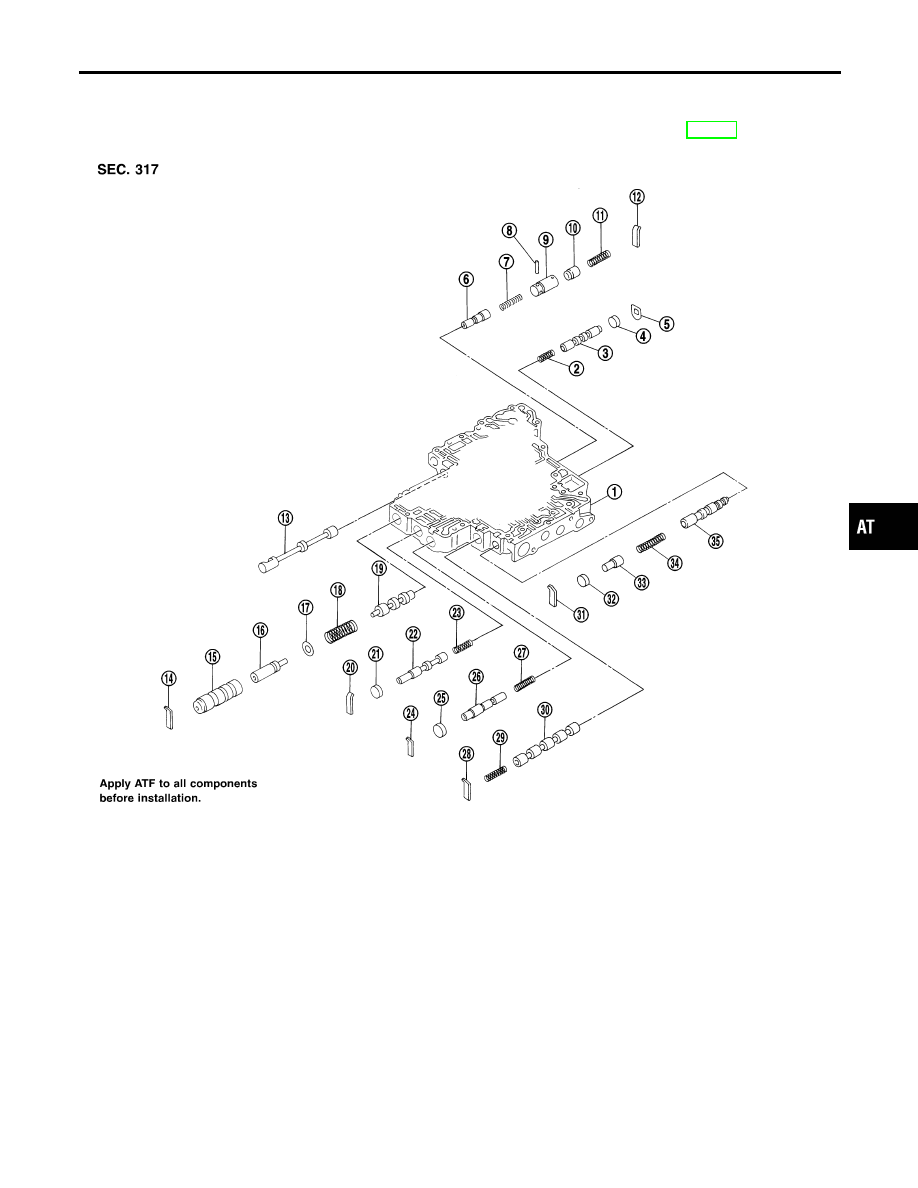
COMPONENTS
=NCAT0137
Numbers preceding valve springs correspond with those shown in SDS table on page AT-390.
SAT864J
1.
Control valve lower body
2.
Return spring
3.
Shift valve B
4.
Plug
5.
Retainer plate
6.
Pressure modifier valve
7.
Return spring
8.
Parallel pin
9.
Sleeve
10. Piston
11. Return spring
12. Retainer plate
13. Manual valve
14. Retainer plate
15. Sleeve
16. Plug
17. Spring seat
18. Return spring
19. Pressure regulator valve
20. Retainer plate
21. Plug
22. Overrun clutch control valve
23. Return spring
24. Retainer plate
25. Plug
26. Accumulator control valve
27. Return spring
28. Retainer plate
29. Return spring
30. Shift valve A
31. Retainer plate
32. Plug
33. Plug
34. Return spring
35. Shuttle control valve
GI
MA
EM
LC
EC
FE
CL
MT
AX
SU
BR
ST
RS
BT
HA
SC
EL
IDX
REPAIR FOR COMPONENT PARTS
Control Valve Lower Body
AT-325