Infiniti G20 (P11). Manual - part 54
 

  Index      Infiniti     Infiniti G20 (P11) - service repair manual 1999-2002 year


Search            


Content   ..  52  53  54  55   ..


Infiniti G20 (P11). Manual - part 54


4

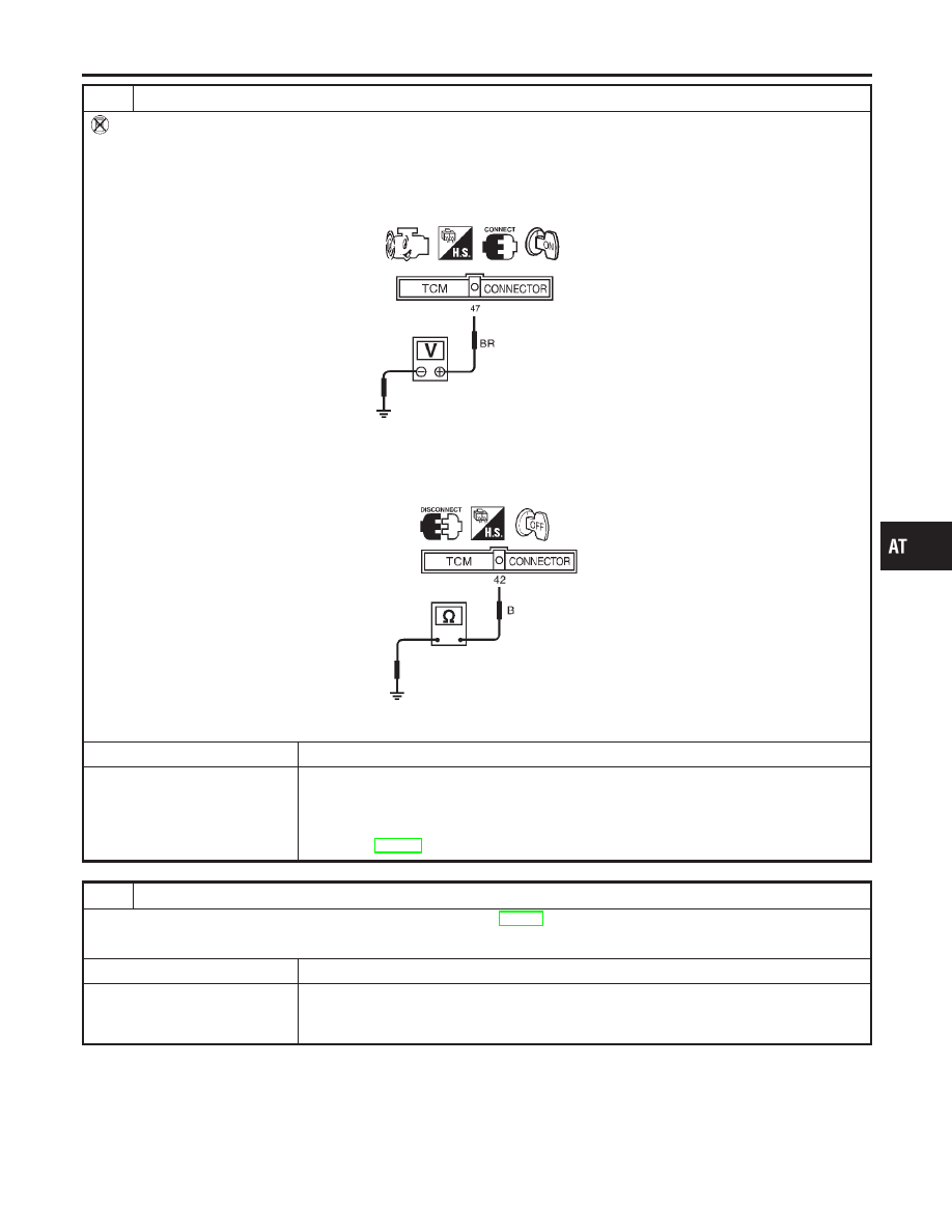
CHECK INPUT SIGNAL OF A/T FLUID TEMPERATURE SENSOR (WITHOUT CONSULT-II)

Without CONSULT-II

1. Start engine.
2. Check voltage between TCM terminal 47 and ground while warming up A/T.

Voltage:

Cold [20°C (68°F)]

→

Hot [80°C (176°F)]:

Approximately 1.5V

→

0.5V

SAT463J

3. Turn ignition switch to “OFF” position.
4. Disconnect TCM harness connector.
5. Check resistance between terminal 42 and ground.

Continuity should exist.

SAT464J

OK or NG

OK

©

GO TO 5.

NG

©

Check the following item:

I

Harness for short or open between TCM, ECM and terminal cord assembly (Main har-
ness)

I

Ground circuit for ECM
Refer to EC-147, “TROUBLE DIAGNOSIS FOR POWER SUPPLY”.

5

CHECK DTC

Perform Diagnostic Trouble Code (DTC) confirmation procedure, AT-209.

OK or NG

OK

©

INSPECTION END

NG

©

1. Perform TCM input/output signal inspection.
2. If NG, recheck TCM pin terminals for damage or loose connection with harness con-

nector.

GI

MA

EM

LC

EC

FE

CL

MT

AX

SU

BR

ST

RS

BT

HA

SC

EL

IDX

DTC BATT/FLUID TEMP SEN (A/T FLUID TEMP SENSOR CIRCUIT AND TCM

POWER SOURCE)

Diagnostic Procedure (Cont’d)

AT-213

SAT298F

Component Inspection

NCAT0078

A/T FLUID TEMPERATURE SENSOR

NCAT0078S01

I

For removal, refer to AT-280.

I

Check resistance between two terminals while changing tem-
perature as shown at left.

Temperature °C (°F)

Resistance

20 (68)

Approximately 2.5 k

Ω

80 (176)

Approximately 0.3 k

Ω

DTC BATT/FLUID TEMP SEN (A/T FLUID TEMP SENSOR CIRCUIT AND TCM

POWER SOURCE)

Component Inspection

AT-214

SAT801I

Description

NCAT0079

The vehicle speed sensor·MTR is built into the speedometer
assembly. The sensor functions as an auxiliary device to the revo-
lution sensor when it is malfunctioning. The TCM will then use a
signal sent from the vehicle speed sensor·MTR.

TCM TERMINALS AND REFERENCE VALUE

NCAT0079S01

Remarks: Specification data are reference values.

Terminal

No.

Wire color

Item

Condition

Judgement stan-

dard

40

Y/G

Vehicle speed sen-
sor

When moving vehicle at 2 to 3
km/h (1 to 2 MPH) for 1 m (3 ft) or
more.

Voltage varies
between less
than 1V and
more than 4.5V

ON BOARD DIAGNOSIS LOGIC

NCAT0079S02

Diagnostic trouble code

Malfunction is detected when ...

Check items (Possible cause)

: VHCL SPEED SEN·MTR

TCM does not receive the proper voltage
signal from the sensor.

I

Harness or connectors
(The sensor circuit is open or shorted.)

I

Vehicle speed sensor

: 2nd judgement flicker

GI

MA

EM

LC

EC

FE

CL

MT

AX

SU

BR

ST

RS

BT

HA

SC

EL

IDX

DTC VHCL SPEED SEN·MTR VEHICLE SPEED SENSOR·MTR

Description

AT-215

SAT014K

SAT971J

SAT329HA

DIAGNOSTIC TROUBLE CODE (DTC) CONFIRMATION
PROCEDURE

NCAT0079S03

CAUTION:

I

Always drive vehicle at a safe speed.

I

If conducting this “DTC CONFIRMATION PROCEDURE”
again, always turn ignition switch “OFF” and wait at least
5 seconds before continuing.

After the repair, perform the following procedure to confirm the
malfunction is eliminated.

With CONSULT-II

1)

Turn ignition switch “ON” and select “DATA MONITOR” mode
for “A/T” with CONSULT-II.

2)

Start engine and accelerate vehicle from 0 to 25 km/h (0 to 16
MPH).

Without CONSULT-II

1)

Start engine.

2)

Drive vehicle under the following conditions:
Selector lever in “D” and vehicle speed higher than 25 km/h (16
MPH).

3)

Perform self-diagnosis.
Refer to TCM SELF-DIAGNOSTIC PROCEDURE (No Tools),
AT-49.

DTC VHCL SPEED SEN·MTR VEHICLE SPEED SENSOR·MTR

Description (Cont’d)

AT-216


Content   ..  52  53  54  55   ..