Infiniti G20 (P11). Manual - part 49
SAT413J
Description
NCAT0070
I
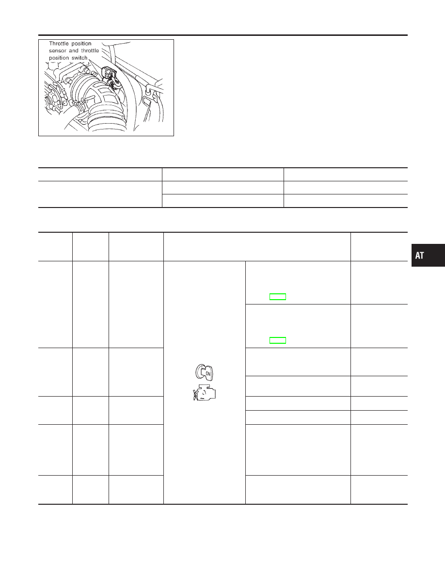
Throttle position sensor
The throttle position sensor detects the throttle valve position
and sends a signal to the TCM.
I
Throttle position switch
Consists of a wide open throttle position switch and a closed
throttle position switch.
The wide open throttle position switch sends a signal to the
TCM when the throttle valve is open at least 1/2 of the full
throttle position. The closed throttle position switch sends a
signal to the TCM when the throttle valve is fully closed.
CONSULT-II REFERENCE VALUE IN DATA MONITOR
MODE
NCAT0070S01
Remarks: Specification data are reference values.
Monitor item
Condition
Specification
Throttle position sensor
Fully-closed throttle
Approximately 0.5V
Fully-open throttle
Approximately 4V
TCM TERMINALS AND REFERENCE VALUE
NCAT0070S02
Remarks: Specification data are reference values.
Terminal
No.
Wire color
Item
Condition
Judgement stan-
dard
(Approx.)
16
Y
Closed throttle
position switch
(in throttle posi-
tion switch)
When releasing accelerator pedal
after warming up engine.
Refer to “Preparation”, “TCM SELF-
DIAGNOSTIC PROCEDURE (No
Tools)”, AT-49.
Battery voltage
When depressing accelerator pedal
after warming up engine.
Refer to “Preparation”, “TCM SELF-
DIAGNOSTIC PROCEDURE (No
Tools)”, AT-49.
0V
17
LG
Wide open
throttle position
switch
(in throttle posi-
tion switch)
When depressing accelerator pedal
more than half-way after warming
up engine.
Battery voltage
When releasing accelerator pedal
after warming up engine.
0V
32
P/L
Throttle position
sensor
(Power source)
Ignition switch “ON”.
4.5 - 5.5V
Ignition switch “OFF”.
0V
41
GY
Throttle position
sensor
When depressing accelerator pedal
slowly after warming up engine.
(Voltage rises gradually in response
to throttle position.)
Fully-closed
throttle:
0.5V
Fully-open
throttle:
4V
42
B
Ground
(Throttle position
sensor)
—
—
GI
MA
EM
LC
EC
FE
CL
MT
AX
SU
BR
ST
RS
BT
HA
SC
EL
IDX
DTC P1705 THROTTLE POSITION SENSOR
Description
AT-193