Infiniti FX35 / FX45. Manual - part 891


  Index      Infiniti     Infiniti FX35 / FX45 (S50) - service repair manual 2008 year


Search            


Content   ..  889  890  891  892   ..


Infiniti FX35 / FX45. Manual - part 891


REAR FINAL DRIVE ASSEMBLY

RFD-19

< SERVICE INFORMATION >

C

E

F

G

H

I

J

K

L

M

A

B

RFD

N

O

P

2.

Remove side flanges.

3.

Rotate drive pinion back and forth 2 to 3 times to check for unusual noise and rotation malfunction.

4.

Rotate drive pinion at least 20 times to check for smooth operation of the bearing.

5.

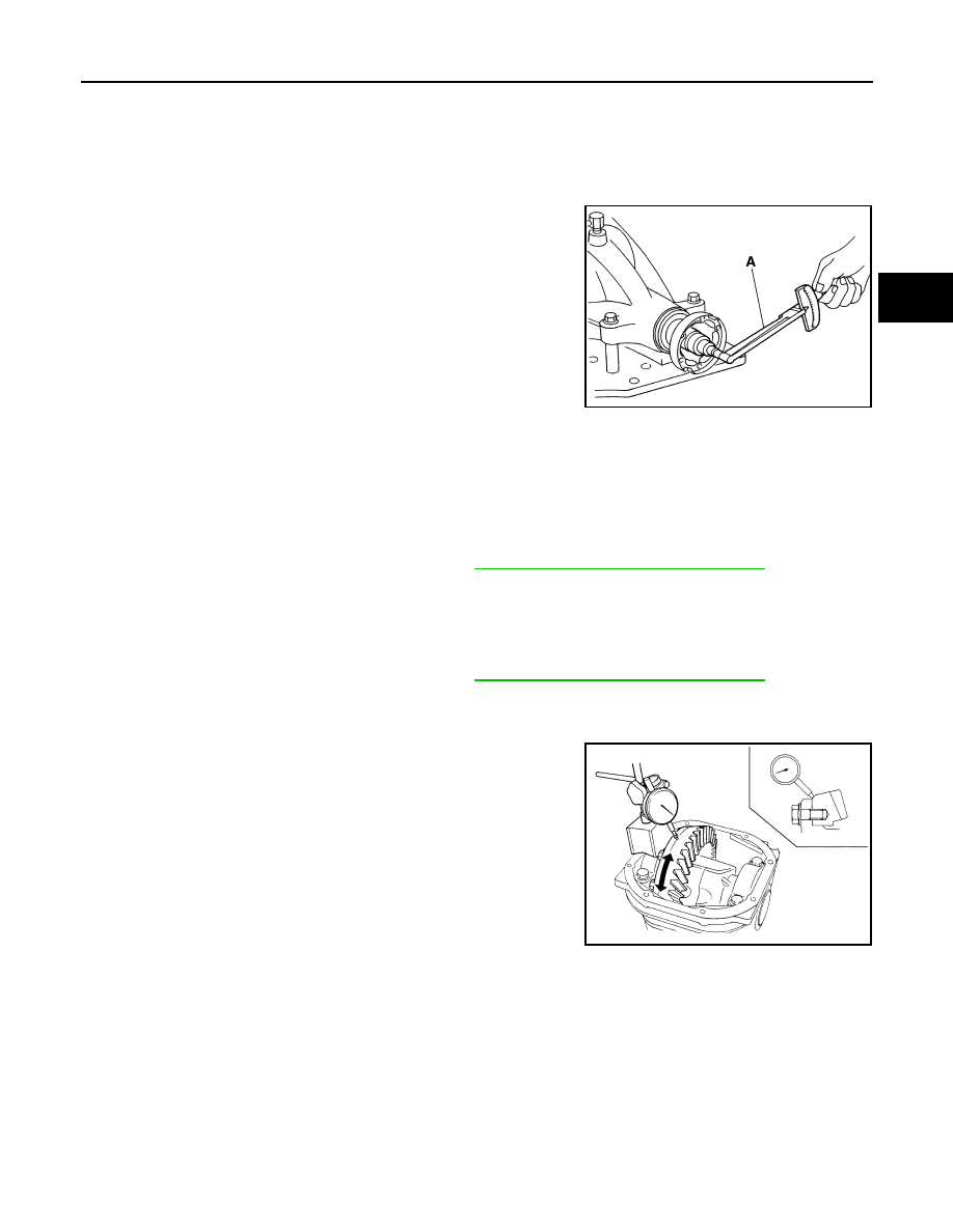
Measure total preload with the preload gauge.

NOTE:
Total preload torque = Pinion bearing preload torque + Side
bearing preload torque

• If measured value is out of the specification, disassemble it to

check and adjust each part. Adjust the pinion bearing preload and
side bearing preload.
Adjust the pinion bearing preload first, then adjust the side bearing preload.

Drive Gear Runout

1.

Remove rear cover. Refer to "Differential Assembly".

2.

Fit a dial indicator to the drive gear back face.

3.

Rotate the drive gear to measure runout.

• If the runout is outside of the repair limit, check drive gear assem-

bly condition; foreign material may be caught between drive gear
and differential case, or differential case or drive gear may be
deformed, etc.

CAUTION:

Replace drive gear and drive pinion gear as a set.

Tooth Contact

1.

Remove rear cover. Refer to "Differential Assembly".

Tool number

A: KV38100800 (J-25604-01)

Tool number

A: ST3127S000 (J-25765-A)

Total preload torque:

2.85 - 3.75 N·m (0.29 - 0.38 kg-m, 26 - 33 in-lb)

PDIA0766J

When the preload torque is large

On pinion bearings:

Replace the collapsible spacer.

On side bearings:

Use thinner side bearing adjusting washers by the same amount to 
each side. Refer to 

RFD-38, "Inspection and Adjustment"

.

When the preload is small

On pinion bearings:

Tighten the drive pinion lock nut.

On side bearings:

Use thicker side bearing adjusting washers by the same amount to 
each side. Refer to 

RFD-38, "Inspection and Adjustment"

.

Runout limit:

0.05 mm (0.0020 in)

SPD886

RFD-20

< SERVICE INFORMATION >

REAR FINAL DRIVE ASSEMBLY

2.

Apply red lead to drive gear.

CAUTION:

Apply red lead to both the faces of 3 to 4 gears at 4 loca-
tions evenly spaced on drive gear.

3.

Rotate drive gear back and forth several times, check drive pin-
ion gear to drive gear tooth contact.

CAUTION:

Check tooth contact on drive side and reverse side.

SPD357

SDIA0570E

SDIA0207E

REAR FINAL DRIVE ASSEMBLY

RFD-21

< SERVICE INFORMATION >

C

E

F

G

H

I

J

K

L

M

A

B

RFD

N

O

P

4.

If tooth contact is improperly adjusted, follow the procedure
below to adjust the pinion height (dimension X).

• If the tooth contact is near the face (face contact), or near the heel

(heel contact), thicken pinion height adjusting washers to move
drive pinion closer to drive gear.
Refer to 

RFD-38, "Inspection and Adjustment"

.

• If the tooth contact is near the flank (flank contact), or near the toe

(toe contact), thin pinion height adjusting washers to move drive
pinion farther from drive gear.
Refer to 

RFD-38, "Inspection and Adjustment"

.

Backlash

1.

Remove rear cover. Refer to "Differential Assembly".

2.

Fit a dial indicator to the drive gear face to measure the back-
lash.

• If the backlash is outside of the specified value, change the thick-

ness of side bearing adjusting washer.

CAUTION:

SDIA0517E

PDIA0440E

PDIA0441E

Backlash:

0.10 - 0.15 mm (0.0039 - 0.0059 in)

When the backlash is large:

Make drive gear back side adjusting washer thicker, 
and drive gear tooth side adjusting washer thinner by 
the same amount. Refer to 

RFD-38, "Inspection and 

Adjustment"

.

When the backlash is small:

Make drive gear back side adjusting washer thinner, 
and drive gear tooth side adjusting washer thicker by 
the same amount. Refer to 

RFD-38, "Inspection and 

Adjustment"

.

SPD513

RFD-22

< SERVICE INFORMATION >

REAR FINAL DRIVE ASSEMBLY

Never change the total amount of washers as it will change the bearing preload.

Companion Flange Runout

1.

Fit a test indicator to the inner side of companion flange (socket
diameter).

2.

Rotate companion flange to check for runout.

3.

If the runout value is outside the runout limit, follow the proce-
dure below to adjust.

a.

Check for runout while changing the phase between companion
flange and drive pinion by 90

°

 step, and search for the position

where the runout is the minimum.

b.

If the runout value is still outside of the limit after the phase has
been changed, possible cause will be an assembly malfunction of drive pinion and pinion bearing and
malfunction of pinion bearing. Check for these items and repair if necessary.

c.

If the runout value is still outside of the limit after the check and repair, replace companion flange.

DISASSEMBLY

Differential Assembly

1.

Drain gear oil, if necessary.

2.

Remove side flange.

3.

Remove rear cover mounting bolts.

4.

Remove rear cover to insert the seal cutter between gear carrier
and rear cover.

CAUTION:

• Be careful not to damage the mating surface.
• Never insert flat-bladed screwdriver, this way damage the

mating surface.

5.

Using two 45 mm (1.77 in) spacers, mount carrier on the attach-
ment.

Runout limit:

0.08 mm (0.0031 in)

PDIA0490E

Tool number

A: KV10111100 (J-37228)

PDIA0756J

Tool number

A: KV38100800 (J-25604-01)

PDIA0757J


Content   ..  889  890  891  892   ..