Infiniti FX35 / FX45. Manual - part 792
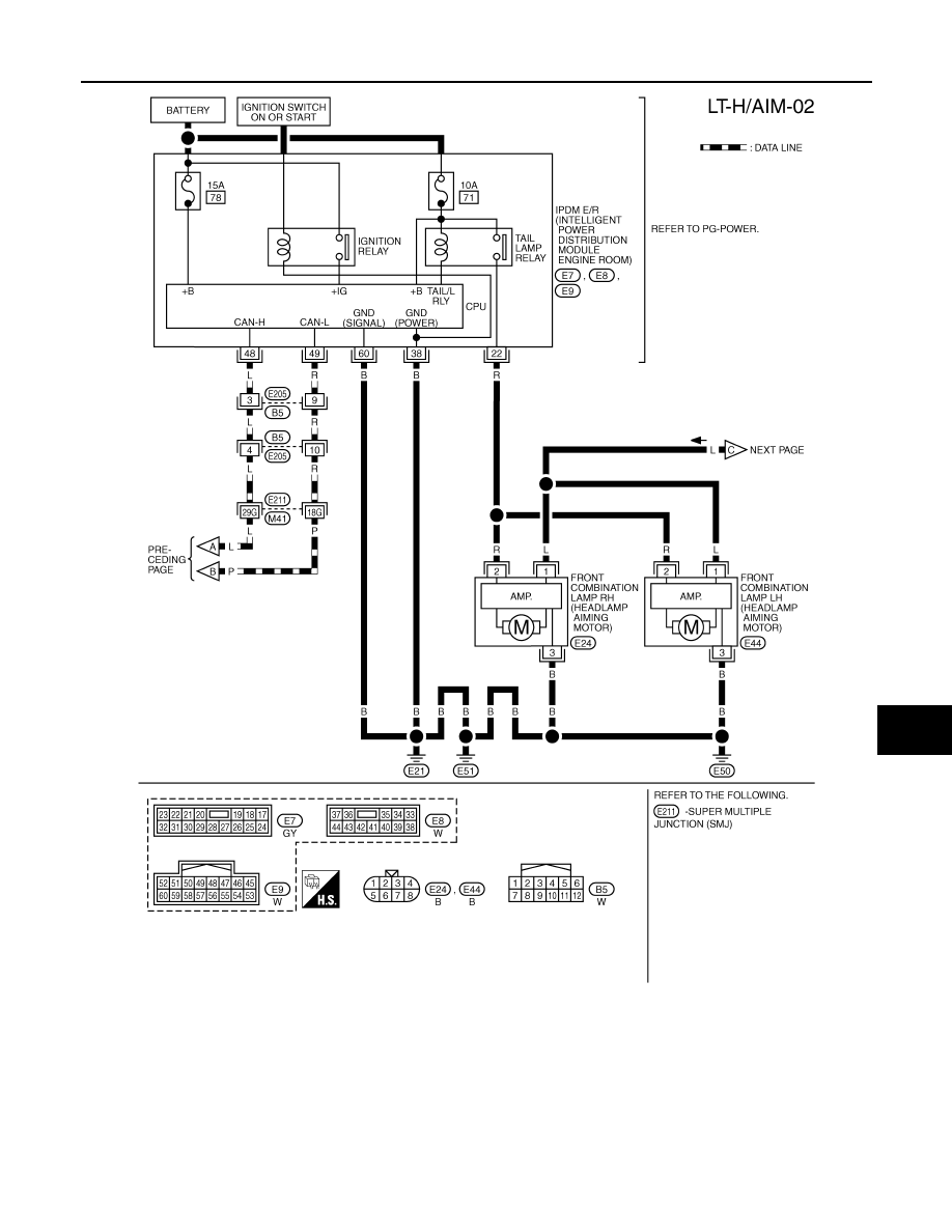
HEADLAMP AIMING CONTROL
LT-63
< SERVICE INFORMATION >
C
D
E
F
G
H
I
J
L
M
A
B
LT
N
O
P
TKWM4301E
|
|
|
HEADLAMP AIMING CONTROL LT-63 < SERVICE INFORMATION > C D E F G H I J L M A B LT N O P TKWM4301E |