Infiniti FX35 / FX45. Manual - part 790


  Index      Infiniti     Infiniti FX35 / FX45 (S50) - service repair manual 2008 year


Search            


Content   ..  788  789  790  791   ..


Infiniti FX35 / FX45. Manual - part 790


AUTO LIGHT SYSTEM

LT-55

< SERVICE INFORMATION >

C

D

E

F

G

H

I

J

L

M

A

B

LT

N

O

P

5.

Does auto light system operate normally? If YES, GO TO 6. If NO, GO TO 4.

6.

INSPECTION END

Preliminary Check

INFOID:0000000001328316

SETTING CHANGE FUNCTIONS

Sensitivity of auto light system can be adjusted using CONSULT-III. Refer to 

LT-56, "CONSULT-III Functions

(BCM)"

.

CHECK POWER SUPPLY AND GROUND CIRCUIT

1.

CHECK FUSES

Check for blown fuses.

Refer to 

LT-50, "Wiring Diagram - AUTO/L -"

.

OK or NG

OK

>> GO TO 2.

NG

>> If fuse is blown, be sure to eliminate cause of malfunction before installing new fuse. Refer to 

PG-

3

.

2.

CHECK POWER SUPPLY CIRCUIT 

1.

Turn ignition switch OFF.

2.

Disconnect BCM connector.

3.

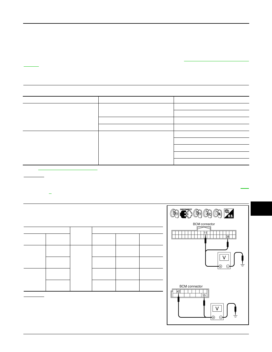
Check voltage between BCM harness connector and ground.

OK or NG

OK

>> GO TO 3.

NG

>> Repair harness or connector.

3.

CHECK GROUND CIRCUIT

Unit

Power source

Fuse and fusible link No.

BCM

Battery

M

22

Ignition switch ON or START position

1

Ignition switch ACC or ON position

6

IPDM E/R

Battery

71

72

74

76

86

(+)

(-)

Ignition switch position

BCM con-

nector

Terminal

OFF

ACC

ON

M3

11

Ground

Approx. 0 V

Battery volt-

age

Battery volt-

age

38

Approx. 0 V

Approx. 0 V

Battery volt-

age

M4

42

Battery volt-

age

Battery volt-

age

Battery volt-

age

55

Battery volt-

age

Battery volt-

age

Battery volt-

age

PKIA5204E

LT-56

< SERVICE INFORMATION >

AUTO LIGHT SYSTEM

Check continuity between BCM harness connector and ground.

OK or NG

OK

>> INSPECTION END

NG

>> Repair harness or connector.

CONSULT-III Functions (BCM)

INFOID:0000000001328317

CONSULT-III can display each diagnostic item using the diagnostic test mode shown following.

CONSULT-III BASIC OPERATION

Refer to 

GI-34, "Description"

.

WORK SUPPORT

Work Support Setting Item

DATA MONITOR

Display Item List

BCM connector

Terminal

Ground

Continuity

M4

49

Yes

52

SKIA5294E

BCM diagnosis part

Diagnosis mode

Description

HEADLAMP

WORK SUPPORT

Changes the setting for each function.

DATA MONITOR

Displays BCM input data in real time.

ACTIVE TEST

Operation of electrical loads can be checked by sending drive signal to them.

BCM

SELF-DIAG RESULTS

BCM performs self-diagnosis of CAN communication.

CAN DIAG SUPPORT MNTR

The result of transmit/receive diagnosis of CAN communication can be read.

Work item

Description

CUSTOM A/LIGHT 

SETTING

Auto light sensitivity can be changed in this mode. Sensitivity can be adjusted in four modes.
• MODE 1 (Normal)/ MODE 2 (sensitive)/MODE 3 (Desensitized)/MODE4 (Insensitive)

ILL DELAY SET

Auto light delay off timer period can be changed in this mode. Selects auto light delay off timer period among eight 
modes.
• MODE 1 (45 sec.)/MODE 2 (OFF)/MODE 3 (30 sec.)/MODE 4 (60 sec.)/MODE 5 (90 sec.)/MODE 6 (120 sec.)/

MODE 7 (150 sec.)/MODE 8 (180 sec.)

Monitor item

Contents

IGN ON SW

“ON/OFF”

Displays “IGN position (ON)/OFF, ACC position (OFF)” judged from ignition switch signal.

ACC ON SW

“ON/OFF”

Displays “ACC (ON)/OFF, Ignition OFF (OFF)” status judged from ignition switch signal.

HI BEAM SW

“ON/OFF”

Displays status (high beam switch: ON/Others: OFF) of high beam switch judged from light-
ing switch signal.

HEAD LAMP SW 1

“ON/OFF”

Displays status (headlamp switch 1: ON/Others: OFF) of headlamp switch 1 judged from 
lighting switch signal. 

HEAD LAMP SW 2

“ON/OFF”

Displays status (headlamp switch 2: ON/Others: OFF) of headlamp switch 2 judged from 
lighting switch signal.

LIGHT SW 1 ST

“ON/OFF”

Displays status (lighting switch 1ST or 2ND position: ON/Others: OFF) of lighting switch 
judged from lighting switch signal.

AUTO LIGHT SW 

NOTE 1 

“ON/OFF”

Displays status of lighting switch as judged from lighting switch signal. (AUTO position: ON/
Other than AUTO position: OFF)

PASSING SW

“ON/OFF”

Displays status (flash-to-pass switch: ON/Others: OFF) of flash-to-pass switch judged from 
lighting switch signal.

AUTO LIGHT SYSTEM

LT-57

< SERVICE INFORMATION >

C

D

E

F

G

H

I

J

L

M

A

B

LT

N

O

P

NOTE:

1.

Vehicles without auto light system display this item, but cannot be monitored.

2.

Vehicles without daytime light system display this item, but cannot be monitored.

3.

This item is displayed, but cannot be monitored.

ACTIVE TEST

Display Item List

NOTE:

1.

Vehicles without daytime light lamp system display this item, but cannot be tested.

2.

This item is displayed, but cannot be tested.

CONSULT-III Functions (IPDM E/R)

INFOID:0000000001328318

CONSULT-III can display each diagnostic item using the diagnostic test mode shown following.

CONSULT-III BASIC OPERATION

Refer to 

GI-34, "Description"

.

FR FOG SW

“ON/OFF”

Displays status (front fog lamp switch: ON/Others: OFF) of front fog lamp switch judged 
from lighting switch signal.

RR FOG SW 

NOTE 3

“OFF”

DOOR SW - DR

“ON/OFF”

Displays status of driver door as judged from driver door switch signal. (Door is open: ON/
Door is closed: OFF)

DOOR SW - AS

“ON/OFF”

Displays status of passenger door as judged from passenger door switch signal. (Door is 
open: ON/Door is closed: OFF)

DOOR SW - RR

“ON/OFF”

Displays status of rear door as judged from rear door switch (RH) signal. (Door is open: ON/
Door is closed: OFF)

DOOR SW - RL

“ON/OFF”

Displays status of rear door as judged from rear door switch (LH) signal. (Door is open: ON/
Door is closed: OFF)

BACK DOOR SW 

“ON/OFF”

Displays status of back door as judged from back door switch signal. (Door is open: ON/
Door is closed: OFF)

TURN SIGNAL R

“ON/OFF”

Displays status (Turn right: ON/Others: OFF) as judged from lighting switch signal.

TURN SIGNAL L

“ON/OFF”

Displays status (Turn left: ON/Others: OFF) as judged from lighting switch signal.

ENGINE RUN 

NOTE 2

“ON/OFF”

Displays status (Engine running: ON/Others: OFF) as judged from engine status signal.

PKB SW 

NOTE 2

“ON/OFF”

Displays status (Parking brake switch: ON/Others: OFF) as judged from parking brake 
switch signal.

CARGO LAMP SW

 NOTE 3


“OFF”

OPTICAL SENSOR 

NOTE 1

 “0 – 5 V” 

Displays “outside brightness (close to 5 V when light/close to 0 V when dark)” judged from 
optical sensor signal.

Monitor item

Contents

Test item

Description

TAIL LAMP

Allows tail lamp relay to operate by switching ON-OFF.

HEAD LAMP 

Allows headlamp relay to operate by switching ON-OFF.

FR FOG LAMP

Allows fog lamp relay to operate by switching ON-OFF.

DTRL 

NOTE 1

Allows day time light lamp operate by switching ON-OFF.

CORNERING LAMP 

NOTE 2

Check Item, Diagnosis Mode

Description

SELF-DIAGNOSTIC RESULTS

Refer to 

PG-18, "CONSULT-III Function (IPDM E/R)"

.

DATA MONITOR

The input/output data of IPDM E/R is displayed in real time.

CAN DIAG SUPPORT MNTR

The result of transmit/receive diagnosis of CAN communication can be read.

ACTIVE TEST

IPDM E/R sends a drive signal to electronic components to check their operation.

LT-58

< SERVICE INFORMATION >

AUTO LIGHT SYSTEM

DATA MONITOR

All Signals, Main Signals, Selection From Menu

NOTE:
Perform monitoring of IPDM E/R data with ignition switch ON. When ignition switch is at ACC, the display may
not be correct.

ACTIVE TEST

Symptom Chart

INFOID:0000000001328319

Lighting Switch Inspection

INFOID:0000000001381749

1.

CHECK LIGHTING SWITCH INPUT SIGNAL 

CONSULT-III DATA MONITOR

1.

Select “AUTO LIGHT SW” of BCM (HEAD LAMP) data monitor item.

2.

With operating the lighting switch AUTO, check the monitor status.

CHECK THE COMBINATION SWITCH

Refer to 

LT-104, "Combination Switch Inspection"

.

OK or NG

OK

>> INSPECTION END

NG

>> Check combination switch (lighting switch). Refer to 

LT-104, "Combination Switch Inspection"

.

Item name

CONSULT-III

 screen display

Display 

or unit

Monitor item selection

Description

ALL

SIGNALS

MAIN 

SIGNALS

SELECTION 

FROM MENU

Position lights request

TAIL & CLR REQ

ON/OFF

×

×

×

Signal status input from BCM

Headlamp low beam request

HL LO REQ

ON/OFF

×

×

×

Signal status input from BCM

Headlamp high beam request

HL HI REQ

ON/OFF

×

×

×

Signal status input from BCM

Front fog lights request

FR FOG REQ

ON/OFF

×

×

×

Signal status input from BCM

Test item

CONSULT-III 

screen display

Description

Headlamp relay (HI, LO) output

LAMPS

Allows headlamp relay (HI, LO) to operate by switching operation (OFF, HI ON, 
LO ON) at your option (Head lamp high beam repeats ON-OFF every 1 second).

Front fog lamp relay output

Allows fog lamp relay to operate by switching operation ON-OFF at your option.

Tail lamp relay output

TAIL LAMP

Allows tail lamp relay to operate by switching operation ON-OFF at your option.

Trouble phenomenon

Malfunction system and reference

• Parking, license plate, side marker and tail lamps and head-

lamps will not illuminate when outside of the vehicle be-
comes dark. (Lighting switch 1ST position and 2ND position 
operate normally.) 

• Parking, license plate, side marker and tail lamps and head-

lamp will not go out when outside of the vehicle becomes 
light. (Lighting switch 1ST position and 2nd position operate 
normally.)

• Headlamps go out when outside of the vehicle becomes 

light, but parking lamps stay on.

• Refer  to 

LT-56, "CONSULT-III Functions (BCM)"

.

• Refer  to 

LT-58, "Lighting Switch Inspection"

.

• Refer  to 

LT-59, "Optical sensor System Inspection"

.

If above systems are normal, replace BCM.

Shut off delay feature will not operate.

• CAN communication line inspection between BCM and combination 

meter. Refer to 

PG-24, "U1000 CAN COMM CIRCUIT"

.

• Refer  to 

BL-38, "Check Door Switch"

.

If above system is normal, replace BCM.

When lighting switch is AUTO 
position

: AUTO LIGHT SW ON 


Content   ..  788  789  790  791   ..