Infiniti FX35 / FX45. Manual - part 737


  Index      Infiniti     Infiniti FX35 / FX45 (S50) - service repair manual 2008 year


Search            


Content   ..  735  736  737  738   ..


Infiniti FX35 / FX45. Manual - part 737


GW-32

< SERVICE INFORMATION >

POWER WINDOW SYSTEM

3.

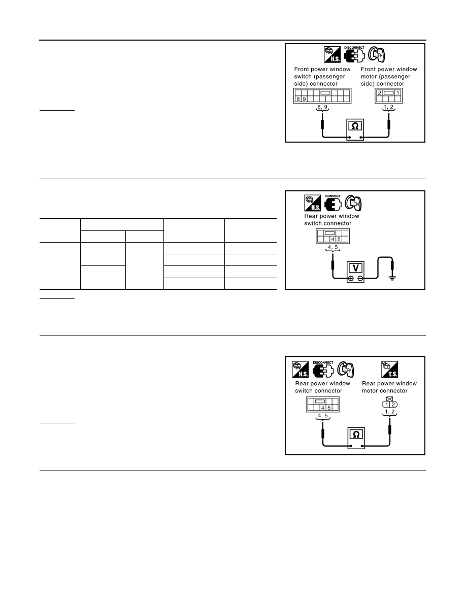
Check continuity between front power window switch (passen-
ger side) connector D36 terminals 8, 9 and front power window
motor (passenger side) connector D38 terminals 1, 2.

OK or NG

OK

>> Replace front power window motor (passenger side).

NG

>> Repair or replace harness.

Check rear Power Window Motor (LH) Circuit

INFOID:0000000001327979

1.

CHECK POWER WINDOW SWITCH OUTPUT SIGNAL

1.

Turn ignition switch ON.

2.

Check voltage between rear power window switch (LH) connec-
tor and ground.

OK or NG

OK

>> GO TO 2.

NG

>> GO TO 3.

2.

CHECK HARNESS CONTINUITY 1

1.

Turn ignition switch OFF.

2.

Disconnect rear power window switch (LH) and rear power window motor (LH) connector.

3.

Check continuity between rear power window switch (LH) con-
nector D55 terminal 4, 5 and rear power window motor (LH) con-
nector D56 terminal 1, 2.

OK or NG

OK

>> Replace rear power window motor (LH).

NG

>> Repair or replace harness.

3.

CHECK REAR POWER WINDOW SWITCH POWER SUPPLY 

1.

Connect rear power window switch (LH) connector.

2.

Turn ignition switch ON.

8 (L) – 2 (L)

: Continuity should exist.

9 (G) – 1 (G)

: Continuity should exist.

PIIA9957E

Connector

Terminals (Wire color)

Window condition

Voltage [V]

(Approx.)

(+)

(-)

D55

4 (L)

Ground

UP

0

DOWN

Battery voltage

5 (G)

UP

Battery voltage

DOWN

0

PIIA6282E

4 (L) – 1 (L)

: Continuity should exist.

5 (G) – 2 (G)

: Continuity should exist.

PIIA9958E

POWER WINDOW SYSTEM

GW-33

< SERVICE INFORMATION >

C

D

E

F

G

H

J

K

L

M

A

B

GW

N

O

P

3.

Check voltage between rear power window switch (LH) connec-
tor D55 terminal 1 and ground.

OK or NG

OK

>> GO TO 5.

NG

>> GO TO 4.

4.

CHECK HARNESS CONTINUITY 2

1.

Turn ignition switch OFF.

2.

Disconnect BCM and rear power window switch (LH) connector.

3.

Check continuity between BCM connector M4 terminal 53 and
rear power window switch (LH) connector D55 terminal 1.

4.

Check continuity between BCM connector M4 terminal 53 and
ground.

OK or NG

OK

>> Check condition of harness and connector.

NG

>> Repair or replace harness.

5.

CHECK REAR POWER WINDOW SWITCH

1.

Turn ignition switch OFF.

2.

Disconnect rear power window switch connector.

3.

Rear power window switch (LH) operate, check continuity
between rear power window switch terminal 1, 2, 3 and 4, 5.

OK or NG

OK

>> GO TO 6.

NG

>> Replace rear power window switch (LH).

6.

CHECK HARNESS CONTINUITY 3

1.

Disconnect power window main switch connector.

2.

Check continuity between power window main switch connector
D6 terminal 1, 3 and rear power window switch (LH) terminal 2,
3.

OK or NG

OK

>> GO TO 7.

NG

>> Repair or replace harness.

7.

CHECK POWER WINDOW MAIN SWITCH OUTPUT SIGNAL

1 (BR) – Ground

: Battery voltage

PIIA4185E

53 (Y/B) – 1 (BR)

: Continuity should exist.

53 (Y/B) – Ground

: Continuity should not exist.

PIIA6284E

Terminals

Window condition

Continuity

1

5

UP

Yes

1

4

DOWN

2

5

No operation

3

4

No operation

PIIA4186E

1 (Y) – 2 (Y)

: Continuity should exist.

3 (R) – 3 (R)

: Continuity should exist.

PIIA4188E

GW-34

< SERVICE INFORMATION >

POWER WINDOW SYSTEM

1.

Connect power window main switch connector.

2.

Turn ignition switch ON.

3.

Rear LH switch in power window main switch is operated, check
voltage between power window main switch connector and
ground.

OK or NG

OK

>> Check condition of harness and connector.

NG

>> Replace power window main switch.

Check Rear Power Window Motor (RH) Circuit

INFOID:0000000001327980

1.

CHECK POWER WINDOW SWITCH OUTPUT SIGNAL

1.

Turn ignition switch ON.

2.

Check voltage between rear power window switch (RH) connec-
tor and ground.

OK or NG

OK

>> GO TO 2.

NG

>> GO TO 3.

2.

CHECK HARNESS CONTINUITY 1

1.

Turn ignition switch OFF.

2.

Disconnect rear power window switch (RH) and rear power window motor (RH) connector.

3.

Check continuity between rear power window switch (RH) con-
nector D75 terminals 4, 5 and rear power window motor (RH)
connector D76 terminals 1, 2.

OK or NG

OK

>> Replace rear power window motor (RH).

NG

>> Repair or replace harness.

3.

CHECK REAR POWER WINDOW SWITCH POWER SUPPLY 

1.

Connect rear power window switch (RH) connector.

2.

Turn ignition switch ON.

Connector

Terminals (Wire color)

Window condition

Voltage [V]

(Approx.)

(+)

(-)

D6

1 (Y)

Ground

UP

Battery voltage

DOWN

0

3 (R)

UP

0

DOWN

Battery voltage

PIIA4187E

Connector

Terminals (Wire color)

Window condition

Voltage [V]

(Approx.)

(+)

(-)

D75

4 (L)

Ground

UP

0

DOWN

Battery voltage

5 (G)

UP

Battery voltage

DOWN

0

PIIA6282E

4 (L) – 1 (L)

: Continuity should exist.

5 (G) – 2 (G)

: Continuity should exist.

PIIA9958E

POWER WINDOW SYSTEM

GW-35

< SERVICE INFORMATION >

C

D

E

F

G

H

J

K

L

M

A

B

GW

N

O

P

3.

Check voltage between rear power window switch (RH) connec-
tor D75 terminal 1 and ground.

OK or NG

OK

>> GO TO 5.

NG

>> GO TO 4.

4.

CHECK HARNESS CONTINUITY 2

1.

Turn ignition switch OFF.

2.

Disconnect BCM and rear power window switch (RH) connector.

3.

Check continuity between BCM connector M4 terminal 53 and
rear power window switch (RH) connector D75 terminal 1.

4.

Check continuity between BCM connector M4 terminal 53 and
ground.

OK or NG

OK

>> Check condition of harness and connector.

NG

>> Repair or replace harness.

5.

CHECK REAR POWER WINDOW SWITCH

1.

Turn ignition switch OFF.

2.

Disconnect rear power window switch connector.

3.

Rear power window switch (RH) operate, check continuity
between rear power window switch terminals1, 2, 3 and 4, 5.

OK or NG

OK

>> GO TO 6.

NG

>> Replace rear power window switch (RH).

6.

CHECK HARNESS CONTINUITY 3

1.

Disconnect power window main switch connector.

2.

Check continuity between power window main switch connector
D6 terminals 5, 7 and rear power window switch (RH) connector
D75 terminals 2, 3.

OK or NG

OK

>> GO TO 7.

NG

>> Repair or replace harness.

7.

CHECK POWER WINDOW MAIN SWITCH OUTPUT SIGNAL

1 (BR) – Ground

: Battery voltage

PIIA4185E

53 (Y/B) – 1 (BR)

: Continuity should exist.

53 (Y/B) – Ground

: Continuity should not exist.

PIIA6284E

Terminals

Window condition

Continuity

1

5

UP

Yes

1

4

DOWN

2

5

No operation

3

4

No operation

PIIA4186E

5 (G) – 3 (R)

: Continuity should exist.

7 (LG) – 2 (Y)

: Continuity should exist.

PIIA4190E


Content   ..  735  736  737  738   ..