Infiniti FX35 / FX45. Manual - part 625
AIR CLEANER AND AIR DUCT
EM-17
< SERVICE INFORMATION >
[VQ35DE]
C
D
E
F
G
H
I
J
K
L
M
A
EM
N
P
O
AIR CLEANER AND AIR DUCT
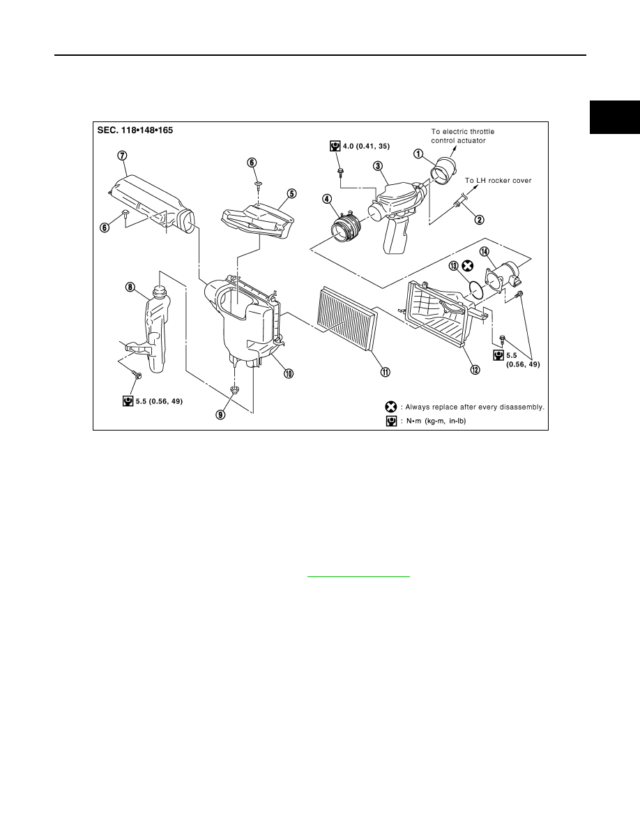
Component
INFOID:0000000001325707
Removal and Installation
INFOID:0000000001325708
REMOVAL
1.
Remove engine cover with power tool. Refer to
• This work is unnecessary when parts located forward of mass air flow sensor are removed/installed.
2.
Remove air duct (inlet) and power duct.
3.
Disconnect mass air flow sensor harness connector.
4.
Disconnect PCV hose.
5.
Remove air cleaner case/mass air flow sensor and air duct disconnecting their joints.
• Add marks as necessary for easier installation.
6.
Remove mass air flow sensor from air cleaner case.
CAUTION:
Handle mass air flow sensor with the following cares.
• Do not shock it.
• Do not disassemble it.
• Do not touch its sensor.
7.
Remove resonator in fender, lifting left fender protector.
INSPECTION AFTER REMOVAL
Inspect air hoses for cracks or tear.
• If anything found replace air hose.
1.
Air hose
2.
PCV hose
3.
Air duct
4.
Air hose
5.
Power duct
6.
Clip
7.
Air duct (inlet)
8.
Resonator
9.
Grommet
10. Air cleaner case
11.
Air cleaner filter
12. Air cleaner case
13. O-ring
14. Mass air flow sensor
SBIA0462E