Infiniti FX35 / FX45. Manual - part 585
DTC P2118 THROTTLE CONTROL MOTOR
EC-1101
< SERVICE INFORMATION >
[VK45DE]
C
D
E
F
G
H
I
J
K
L
M
A
EC
N
P
O
1.
Disconnect electric throttle control actuator (1) harness connec-
tor.
2.
Disconnect ECM harness connector.
3.
Check harness continuity between the following terminals.
Refer to Wiring Diagram.
4.
Also check harness for short to ground and short to power.
OK or NG
OK
>> GO TO 3.
NG
>> Repair or replace.
3.
CHECK THROTTLE CONTROL MOTOR
EC-1101, "Component Inspection"
.
OK or NG
OK
>> GO TO 4.
NG
>> GO TO 5.
4.
CHECK INTERMITTENT INCIDENT
OK or NG
OK
>> GO TO 5.
NG
>> Repair or replace harness or connectors.
5.
REPLACE ELECTRIC THROTTLE CONTROL ACTUATOR
1.
Replace the electric throttle control actuator.
2.
EC-663, "Throttle Valve Closed Position Learning"
3.
EC-663, "Idle Air Volume Learning"
.
>> INSPECTION END
Component Inspection
INFOID:0000000001326994
THROTTLE CONTROL MOTOR
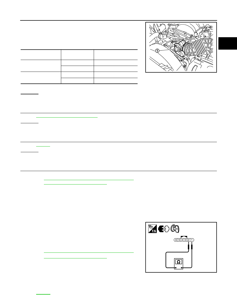
1.
Disconnect electric throttle control actuator harness connector.
2.
Check resistance between terminals 1 and 2.
3.
If NG, replace electric throttle control actuator and go to next
step.
4.
EC-663, "Throttle Valve Closed Position Learning"
5.
EC-663, "Idle Air Volume Learning"
.
Removal and Installation
INFOID:0000000001326995
ELECTRIC THROTTLE CONTROL ACTUATOR
.
Electric throttle control
actuator terminal
ECM terminal
Continuity
1
5
Should exist
4
Should not exist
2
5
Should not exist
4
Should exist
PBIB3232E
Resistance: Approximately 1 - 15
Ω
[at 25
°
C (77
°
F)]
PBIB3251E