Infiniti FX35 / FX45. Manual - part 476


  Index      Infiniti     Infiniti FX35 / FX45 (S50) - service repair manual 2008 year


Search            


Content   ..  474  475  476  477   ..


Infiniti FX35 / FX45. Manual - part 476


BASIC SERVICE PROCEDURE

EC-665

< SERVICE INFORMATION >

[VK45DE]

C

D

E

F

G

H

I

J

K

L

M

A

EC

N

P

O

Fuel Pressure Check

INFOID:0000000001326522

FUEL PRESSURE RELEASE

 With CONSULT-III

1.

Turn ignition switch ON.

2.

Perform “FUEL PRESSURE RELEASE” in “WORK SUPPORT” mode with CONSULT-III.

3.

Start engine.

4.

After engine stalls, crank it two or three times to release all fuel pressure.

5.

Turn ignition switch OFF.

 Without CONSULT-III

1.

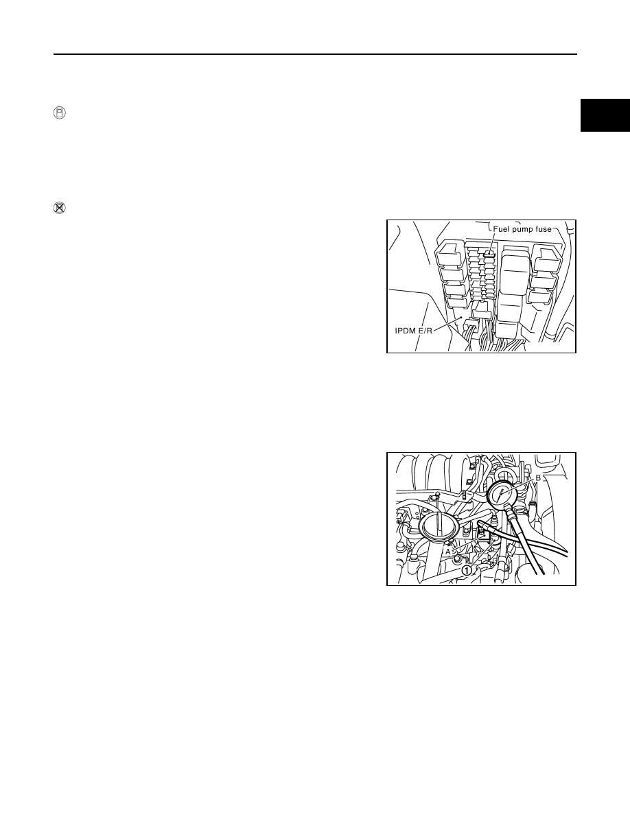
Remove fuel pump fuse located in IPDM E/R.

2.

Start engine.

3.

After engine stalls, crank it 2 or 3 times to release all fuel pres-
sure.

4.

Turn ignition switch OFF.

5.

Reinstall fuel pump fuse after servicing fuel system.

FUEL PRESSURE CHECK

Before disconnecting fuel line, release fuel pressure from fuel line to eliminate danger.
NOTE:
• Prepare pans or saucers under the disconnected fuel line because the fuel may spill out. The fuel

pressure cannot be completely released because S50 models do not have fuel return system.

• Use Fuel Pressure Gauge Kit (J-44321) to check fuel pressure.

1.

Release fuel pressure to zero. Refer to "FUEL PRESSURE RELEASE".

2.

Install the inline fuel quick disconnected fitting A between fuel
damper (1) and fuel tube.

3.

Connect the fuel pressure gauge B (quick connector adapter
hose) to the inline fuel quick disconnected fitting.

4.

Turn ignition switch ON and check for fuel leakage.

5.

Start engine and check for fuel leakage.

6.

Read the indication of fuel pressure gauge.

7.

If result is unsatisfactory, go to next step.

8.

Check the following.
• Fuel hoses and fuel tubes for clogging
• Fuel filter for clogging
• Fuel pump
• Fuel pressure regulator for clogging
If OK, replace fuel level sensor unit, fuel filter and fuel pump assembly.
If NG, repair or replace.

PBIB1482E

At idling:

Approximately 350 kPa (3.57 kg/cm

2

, 51 psi)

PBIB3244E

EC-666

< SERVICE INFORMATION >

[VK45DE]

TROUBLE DIAGNOSIS

TROUBLE DIAGNOSIS

Trouble Diagnosis Introduction

INFOID:0000000001326523

INTRODUCTION

The engine has an ECM to control major systems such as fuel con-
trol, ignition control, idle air control system, etc. The ECM accepts
input signals from sensors and instantly drives actuators. It is essen-
tial that both input and output signals are proper and stable. At the
same time, it is important that there are no malfunctions such as vac-
uum leaks, fouled spark plugs, or other malfunctions with the engine.

It is much more difficult to diagnose an incident that occurs intermit-
tently rather than continuously. Most intermittent incidents are
caused by poor electric connections or improper wiring. In this case,
careful checking of suspected circuits may help prevent the replace-
ment of good parts.

A visual check only may not find the cause of the incidents. A road
test with CONSULT-III (or GST) or a circuit tester connected should
be performed. Follow the Work Flow on "Work Flow".
Before undertaking actual checks, take a few minutes to talk with a
customer who approaches with a driveability complaint. The cus-
tomer can supply good information about such incidents, especially
intermittent ones. Find out what symptoms are present and under
what conditions they occur. A Diagnostic Worksheet like the example
on "Worksheet Sample"  should be used.
Start your diagnosis by looking for conventional malfunctions first.
This will help troubleshoot driveability malfunctions on an electroni-
cally controlled engine vehicle.

WORK FLOW

MEF036D

SEF233G

SEF234G

TROUBLE DIAGNOSIS

EC-667

< SERVICE INFORMATION >

[VK45DE]

C

D

E

F

G

H

I

J

K

L

M

A

EC

N

P

O

Overall Sequence

Detailed Flow

1.

GET INFORMATION FOR SYMPTOM

Get the detailed information from the customer about the symptom (the condition and the environment when
the incident/malfunction occurred) using the "DIAGNOSTIC WORKSHEET".

>> GO TO 2.

PBIB3456E

EC-668

< SERVICE INFORMATION >

[VK45DE]

TROUBLE DIAGNOSIS

2.

CHECK DTC*

1

1.

Check DTC*

1

.

2.

Perform the following procedure if DTC*

1

 is displayed.

-

Record DTC*

1

 and freeze frame data*

2

. (Print them out with CONSULT-III or GST.)

-

Erase DTC*

1

. (Refer to 

EC-633, "Emission-related Diagnostic Information"

.)

-

Study the relationship between the cause detected by DTC*

1

 and the symptom described by the cus-

tomer. (Symptom Matrix Chart is useful. Refer to 

EC-673

.)

3.

Check related service bulletins for information.

Is any symptom described and any DTC detected?

Symptom is described, DTC*

1

 is displayed>>GO TO 3.

Symptom is described, DTC*

1

 is not displayed>>GO TO 4.

Symptom is not described, DTC*

1

 is displayed>>GO TO 5.

3.

CONFIRM THE SYMPTOM

Try to confirm the symptom described by the customer (except MIL ON).
DIAGNOSIS WORK SHEET is useful to verify the incident.
Connect CONSULT-III to the vehicle and check diagnosis results.
Verify relation between the symptom and the condition when the symptom is detected.

>> GO TO 5.

4.

CONFIRM THE SYMPTOM

Try to confirm the symptom described by the customer.
DIAGNOSIS WORK SHEET is useful to verify the incident.
Connect CONSULT-III to the vehicle and check diagnosis results.
Verify relation between the symptom and the condition when the symptom is detected.

>> GO TO 6.

5.

PERFORM DTC CONFIRMATION PROCEDURE

Perform DTC Confirmation Procedure for the displayed DTC*

1

, and then make sure that DTC*

1

 is detected

again.
If two or more DTCs*

1

 are detected, refer to 

EC-670, "DTC Inspection Priority Chart"

 and determine trouble

diagnosis order.
NOTE:
• Freeze frame data*

2

 is useful if the DTC*

1

 is not detected.

• Perform Overall Function Check if DTC Confirmation Procedure is not included on Service Manual. This

simplified check procedure is an effective alternative though DTC*

1

 cannot be detected during this check.

If the result of Overall Function Check is NG, it is the same as the detection of DTC*

1

 by DTC Confirmation

Procedure.

Is DTC*

1

 detected?

Yes

>> GO TO 10.

No

>> Check according to 

EC-717

.

6.

PERFORM BASIC INSPECTION

Perform 

EC-658, "Basic Inspection"

.

With CONSULT-III>>GO TO 7.
Without CONSULT-III>>GO TO 9.

7.

PERFORM SPRC IN DATA MONITOR MODE

 With CONSULT-III

Make sure that “MAS A/F SE-B1”, “B/FUEL SCHDL”, and “A/F ALPHA-B1”, “A/F ALPHA-B2” are within the SP
value using CONSULT-III “SPEC” in “DATA MONITOR” mode. Refer to 

EC-710, "Diagnosis Procedure"

.


Content   ..  474  475  476  477   ..