Infiniti FX35 / FX45. Manual - part 200
REMOTE KEYLESS ENTRY SYSTEM
BL-67
< SERVICE INFORMATION >
C
D
E
F
G
H
J
K
L
M
A
B
BL
N
O
P
Without CONSULT-III
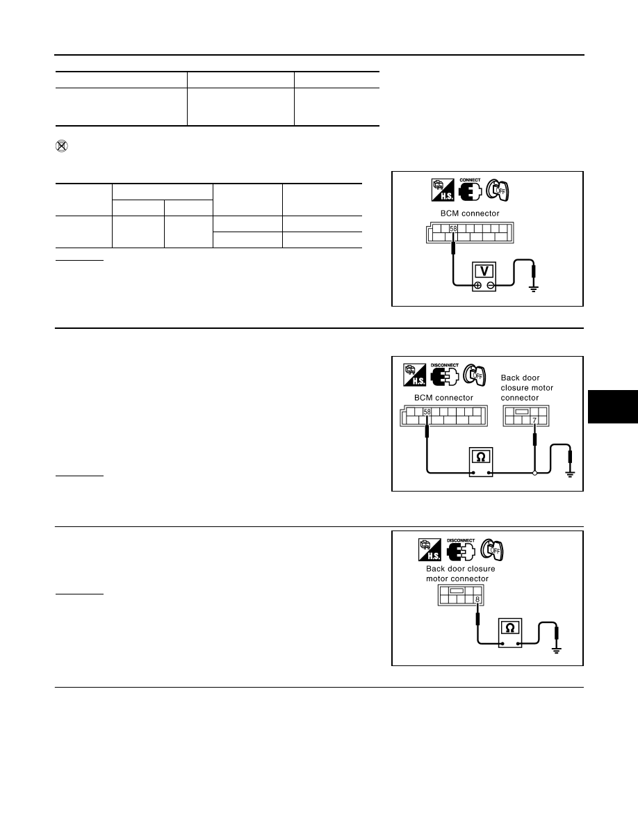
Check voltage between BCM connector and ground.
OK or NG
OK
>> Back door switch circuit is OK.
NG
>> GO TO 2.
2.
CHECK HARNESS CONTINUITY
1.
Turn ignition switch OFF.
2.
Disconnect BCM and back door closure motor connector.
3.
Check continuity between BCM connector B14 terminal 58 and
back door closure motor connector D109 terminal 7.
4.
Check continuity between BCM connector B14 terminal 58 and
ground.
OK or NG
OK
>> GO TO 3.
NG
>> Repair or replace harness.
3.
CHECK GROUND CIRCUIT
Check continuity between back door closure motor connector D109
terminal 8 and ground.
OK or NG
OK
>> GO TO 4.
NG
>> Repair or replace harness.
4.
CHECK BACK DOOR SWITCH
Monitor item
Condition
DATA MONITOR
BACK DOOR SW
OPEN
↓
CLOSE
ON
↓
OFF
Connector
Terminals (Wire color)
Condition
Voltage (V)
(Approx.)
(+)
(–)
B14
58 (L)
Ground
OPEN
0
CLOSE
9
PIIA6229E
58 (L) – 7 (L)
: Continuity should exist.
58 (L) – Ground
: Continuity should not exist.
PIIA6226E
8 (B) – Ground
: Continuity should exist.
PIIA6170E