Infiniti FX35 / FX45. Manual - part 157
AV-82
< SERVICE INFORMATION >
INTEGRATED DISPLAY SYSTEM
4.
Check voltage between display control unit harness connector
M75 terminals 4 and 7.
OK or NG
OK
>> Replace display.
NG
>> Replace display control unit.
5.
CHECK DISPLAY CONTROL UNIT POWER SUPPLY AND GROUND CIRCUIT
1.
Check voltage between display control unit harness connector
terminals and ground.
2.
Turn ignition switch OFF.
3.
Disconnect display control unit connector.
4.
Check continuity between display control unit harness connector
M75 terminal 3 and ground.
OK or NG
OK
>> Replace display control unit.
NG
>> Repair harness or connector.
Tint Is Strange for the RGB Image
INFOID:0000000001328730
Symptom: Tint of all RGB images is strange.
1.
CHECK HARNESS
1.
Turn ignition switch OFF.
2.
Disconnect display control unit and display connectors.
3.
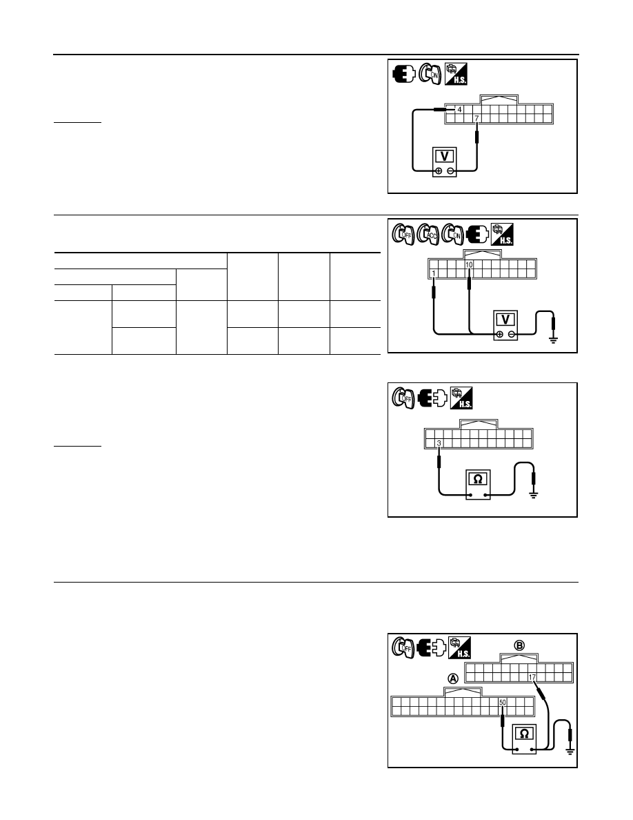
Check the malfunctioning circuit according to the symptoms.
• Light blue (Cyan) tinged screen
Check continuity between display control unit harness connector
(A) M76 terminal 50 and display harness connector (B) M63 termi-
nal 17.
Check continuity between display control unit harness connector
(A) M76 terminal 50 and ground.
4 – 7
: Approx. 9 V
SKIB7842E
Terminals
OFF
ACC
ON
(+)
(–)
Connector
Terminal
M75
1
Ground
Battery
voltage
Battery
voltage
Battery
voltage
10
0 V
Battery
voltage
Battery
voltage
3 – Ground
: Continuity should exist.
SKIB7843E
SKIB7844E
50 – 17
: Continuity should exist.
50 – Ground
: Continuity should not exist.
SKIB7853E