Infiniti FX35, FX50 (S51). Manual - part 963
EM-152
< SERVICE DATA AND SPECIFICATIONS (SDS)
[VQ35HR]
SERVICE DATA AND SPECIFICATIONS (SDS)
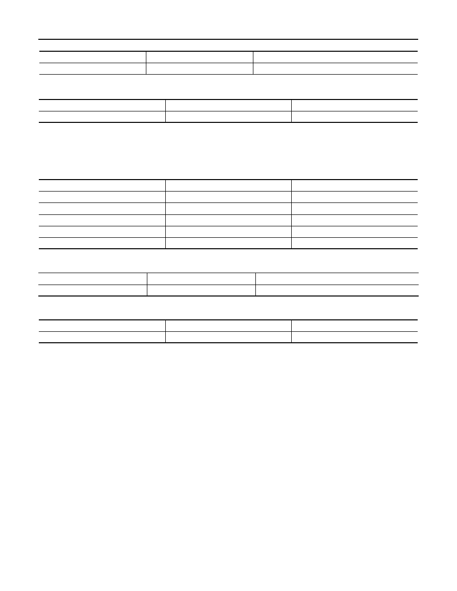
Unit: mm (in)
MAIN BEARING OIL CLEARANCE
Unit: mm (in)
*: Actual clearance
Connecting Rod Bearing
INFOID:0000000005245192
CONNECTING ROD BEARING
Unit: mm (in)
UNDERSIZE
Unit: mm (in)
CONNECTING ROD BEARING OIL CLEARANCE
Unit: mm (in)
*: Actual clearance
Items
Thickness
Main journal diameter
0.25 (0.0098)
2.633 - 2.641 (0.1037 - 0.1040)
Grind so that bearing clearance is the specified value.
Items
Standard
Limit
Main bearing oil clearance
0.035 - 0.045 (0.0014 - 0.0018)*
0.065 (0.0026)
Grade number
Thickness
Identification color (mark)
0
1.497 - 1.500 (0.0589 - 0.0591)
Black
1
1.500 - 1.503 (0.0591 - 0.0592)
Brown
2
1.503 - 1.506 (0.0592 - 0.0593)
Green
3
1.506 - 1.509 (0.0593 - 0.0594)
Yellow
4
1.509 - 1.512 (0.0594 - 0.0595)
Blue
Items
Thickness
Crank pin journal diameter
0.25 (0.0098)
1.626 - 1.634 (0.0640 - 0.0643)
Grind so that bearing clearance is the specified value.
Items
Standard
Limit
Connecting rod bearing oil clearance
0.040 - 0.053 (0.0016 - 0.0021)*
0.070 (0.0028)