Content .. 1616 1617 1618 1619 ..
Infiniti FX35, FX50 (S51). Manual - part 1618
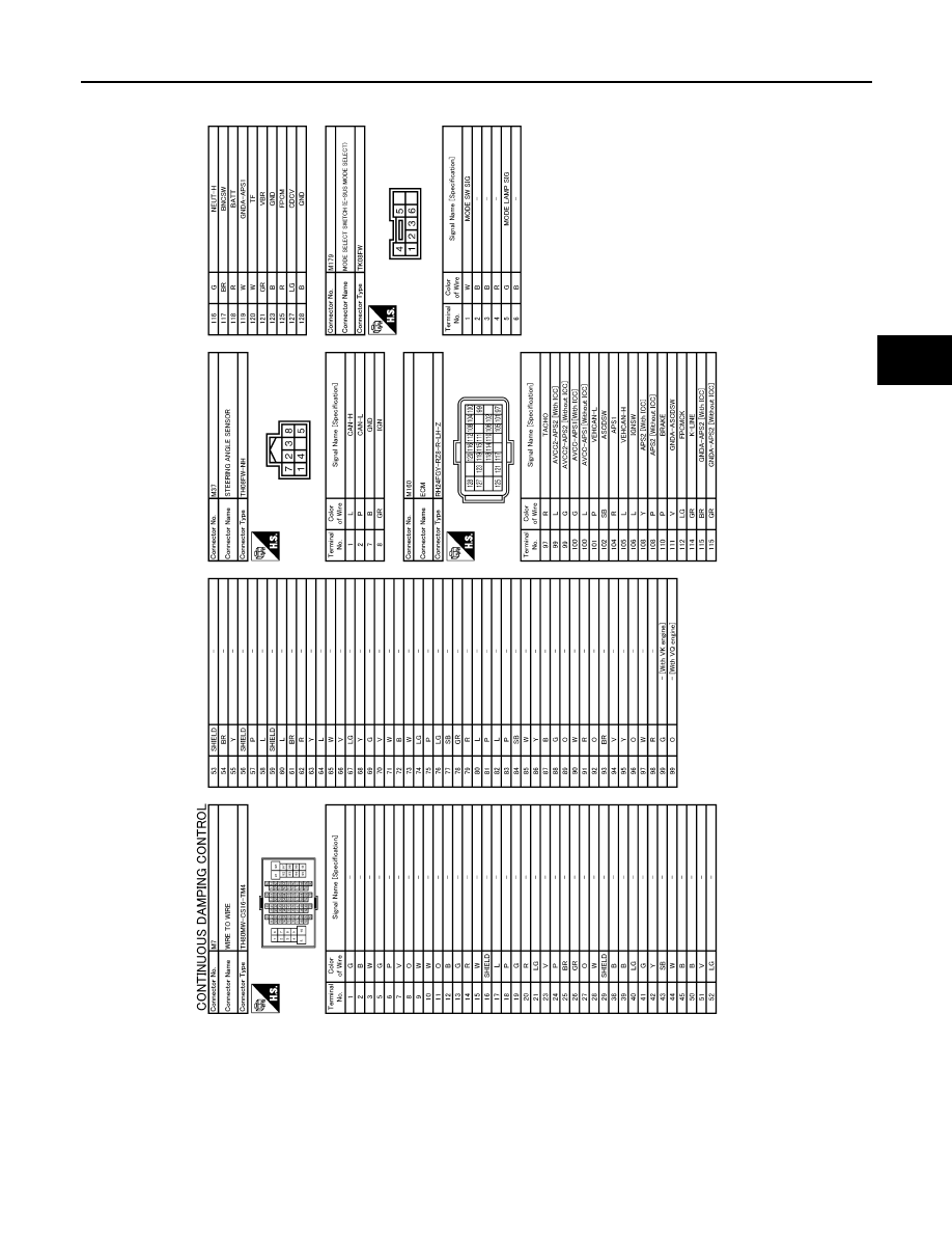
E-SUS CONTROL UNIT
SCS-57
< ECU DIAGNOSIS INFORMATION >
C
D
F
G
H
I
J
K
L
M
A
B
SCS
N
O
P
Fail-safe
INFOID:0000000005236213
Continuous Damping Control system
• When detecting any malfunction in each component of the system, it enters the fail-safe status.
• The damping force is simultaneously maintained at approximately the intermediate level between the maxi-
mum and the minimum values, when entering the fail-safe status.
• Even if the switch is operated in the fail-safe status, lamp illuminates in SPORT mode or AUTO mode.
JCEWA0170GB