Infiniti FX35, FX50 (S51). Manual - part 1616


  Index      Infiniti     Infiniti FX35, FX50 (S51) - service repair manual 2010 year


Search            


Content   ..  1614  1615  1616  1617   ..


Infiniti FX35, FX50 (S51). Manual - part 1616


E-SUS CONTROL UNIT

SCS-49

< ECU DIAGNOSIS INFORMATION >

C

D

F

G

H

I

J

K

L

M

A

B

SCS

N

O

P

ECU DIAGNOSIS INFORMATION

E-SUS CONTROL UNIT

Reference Value

INFOID:0000000005236211

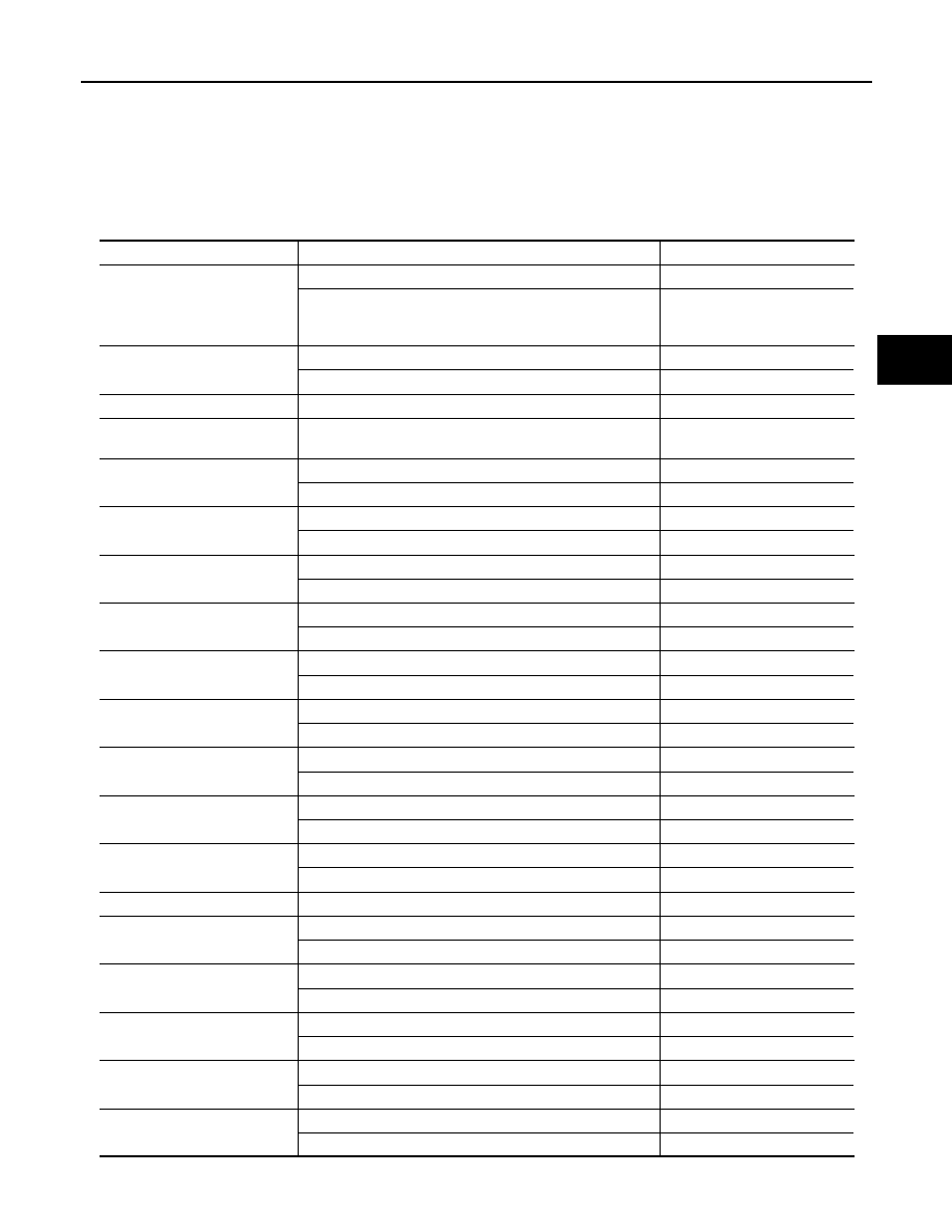
VALUES ON THE DIAGNOSIS TOOL

TERMINAL LAYOUT

Monitor item

Condition

Value/Status

VEHICLE SPEED

Vehicle stopped

0 km/h (MPH)

While driving for a period of time after the engine starts. 

CAUTION:

Check tire pressure in normal condition.

Almost in accordance with the 
speedometer display. (Within 

±

10%)

ST ANGLE SIG

Neutral

Approx. 0 deg

Steering

0 – 780 deg

IGN

Always

Battery voltage

REQUESTED TRQ

• Engine: At idle speed after warm-up
• Selector lever: P or N position

Approx. 26 Nm

FR BDY G-SEN VOL

When stopped

Approx. 2.35 – 2.65 V

While driving

Approx. 0.5 – 4.5 V

FL BDY G-SEN VOL

When stopped

Approx. 2.35 – 2.65 V

While driving

Approx. 0.5 – 4.5 V

R G-SEN VOL

When stopped

Approx. 2.35 – 2.65 V

While driving

Approx. 0.5 – 4.5 V

FR WHL G-SEN VOL

When stopped

Approx. 2.35 – 2.65 V

While driving

Approx. 0.5 – 4.5 V

FL WHL G-SEN VOL

When stopped

Approx. 2.35 – 2.65 V

While driving

Approx. 0.5 – 4.5 V

FR ACTUATOR CRNT

Vehicle stopped

Approx. 0.65 A

While driving

Approx. 0.65 – 2.0 A

FL ACTUATOR CRNT

Vehicle stopped

Approx. 0.65 A

While driving

Approx. 0.65 – 2.0 A

RR ACTUATOR CRNT

Vehicle stopped

Approx. 0.65 A

While driving

Approx. 0.65 – 2.0 A

RL ACTUATOR CRNT

Vehicle stopped

Approx. 0.65 A

While driving

Approx. 0.65 – 2.0 A

G-SEN VOL

Ignition switch ON

Approx. 4.75 – 5.25 V

BRK FLD PRESS

Brake deactivated

Approx. 0 bar

Brake activated

–40 – 300 bar

STP LAMP SW

Depress the brake

On

Do not depress the brake

Off

MODE SW

Sport mode

On

Auto mode

Off

FAIL MODE SIG

Fail-safe mode 

On

Normal mode

Off

CONTROL MODE

Sport mode

SPORT

Auto mode

AUTO

SCS-50

< ECU DIAGNOSIS INFORMATION >

E-SUS CONTROL UNIT

PHYSICAL VALUES

JSEIA0023ZZ

Terminal No.

(Wire color)

Description

Condition

Value (Approx.)

+

-

Signal name

Input/

Output

1

(L)

Ground

E-SUS control unit power supply

Input

Ignition switch ON

Battery voltage

2

(P)

Front RH shock absorber actua-
tor LOW terminal

3

(V)

Front RH shock absorber actua-
tor HI terminal

4

(G)

Front LH shock absorber actuator 
LOW terminal

5

(Y)

Front LH shock absorber actuator 
HI terminal

6

(LG)

Rear LH shock absorber actuator 
HI terminal

7

(V)

Rear LH shock absorber actuator 
LOW terminal

8

(L)

Rear RH shock absorber actuator 
HI terminal

9

(P)

Rear RH shock absorber actuator 
LOW terminal

10

(O)

Ground

Front LH wheel vertical G sensor 
output voltage

Input

Ignition switch ON

Approx. 2.35 – 2.65 V

11

(SB)

Ground

Front RH body vertical G sensor 
output voltage

Input

Ignition switch ON

Approx. 2.35 – 2.65 V

12

(R)

Ground

Front LH body vertical G sensor 
output voltage

Input

Ignition switch ON

Approx. 2.35 – 2.65 V

14

(G)

Ground

Rear body vertical G sensor out-
put voltage

Input

Ignition switch ON

Approx. 2.35 – 2.65 V

17

(L)

Ground

E-SUS control unit power supply

Input

Ignition switch ON

Battery voltage

18

(B)

Ground

Ground

Always

0 V

19

(B)

Ground

Ground

Always

0 V

20

(W)

Mode switch terminal

23

(G)

Mode lamp terminal

24

(W)

Ground

Front RH wheel vertical G sensor 
output voltage

Input

Ignition switch ON

Approx. 2.35 – 2.65 V

E-SUS CONTROL UNIT

SCS-51

< ECU DIAGNOSIS INFORMATION >

C

D

F

G

H

I

J

K

L

M

A

B

SCS

N

O

P

CAUTION:

Never extend connector terminals forcibly, when checking voltage using a circuit tester for voltage inspection. 

25

(Y)

Ground

Rear body vertical G sensor 
ground

Always

0  V

26

(BR)

Ground

Front vertical G sensor ground

Always

0 V

27

(GR)

Ground

Front vertical G sensor power 
supply

Output

Ignition switch ON

Approx. 4.75 – 5.25 V

29

(P)

CAN-L

30

(LG)

Ground

Rear vertical G sensor power 
supply

Output

Ignition switch ON

Approx. 4.75 – 5.25 V

32

(L)

CAN-H

Terminal No.

(Wire color)

Description

Condition

Value (Approx.)

+

-

Signal name

Input/

Output

SCS-52

< ECU DIAGNOSIS INFORMATION >

E-SUS CONTROL UNIT

Wiring Diagram - Continuous Damping Control SYSTEM -

INFOID:0000000005589005

JCEWA0165GB


Content   ..  1614  1615  1616  1617   ..