Infiniti EX35. Manual - part 895
COMPRESSOR
HA-39
< ON-VEHICLE REPAIR >
C
D
E
F
G
H
J
K
L
M
A
B
HA
N
O
P
ON-VEHICLE REPAIR
COMPRESSOR
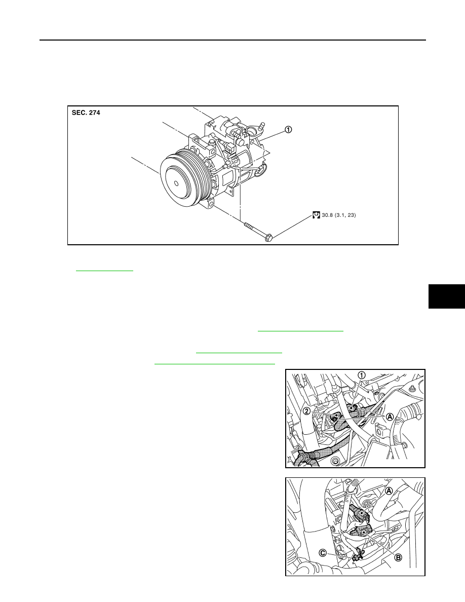
Exploded View
INFOID:0000000003545476
Removal and Installation
INFOID:0000000003545477
REMOVAL
1.
Use a refrigerant collecting equipment (for HFC-134a) to discharge the refrigerant.
2.
Remove air cleaner case (LH) and air duct (LH). Refer to
.
3.
Remove engine undercover, using power tools.
4.
Remove cooling fan assembly. Refer to
5.
Remove drive belt. Refer to
EM-13, "Removal and Installation"
.
6.
Remove mounting nuts (A) from low-pressure flexible hose (1)
and high-pressure flexible hose (2).
CAUTION:
Cap or wrap the joint of the A/C piping and compressor with
suitable material such as vinyl tape to avoid the entry of air.
7.
Disconnect compressor (ECV) connector (A).
8.
Disconnect compressor (magnet clutch) connector (B).
9.
Remove harness clip (C)
1.
Compressor
Refer to
JSIIA0011GB
JPIIA0685ZZ
JPIIA0686ZZ