Infiniti EX35. Manual - part 852
FL-6
< ON-VEHICLE REPAIR >
FUEL LEVEL SENSOR UNIT, FUEL FILTER AND FUEL PUMP ASSEMBLY
a.
Insert hose of less than 25 mm (0.98 in) in diameter into fuel filler tube through fuel filler opening to draw
fuel from fuel filler tube.
b.
Disconnect fuel filler hose from fuel filler tube. Refer to
c.
Insert fuel tube into fuel tank through fuel filler hose to draw fuel from fuel tank.
2.
Release the fuel pressure from the fuel lines. Refer to
3.
Open fuel filler lid.
4.
Open filler cap and release the pressure inside fuel tank.
5.
Remove rear seat cushion. Refer to
.
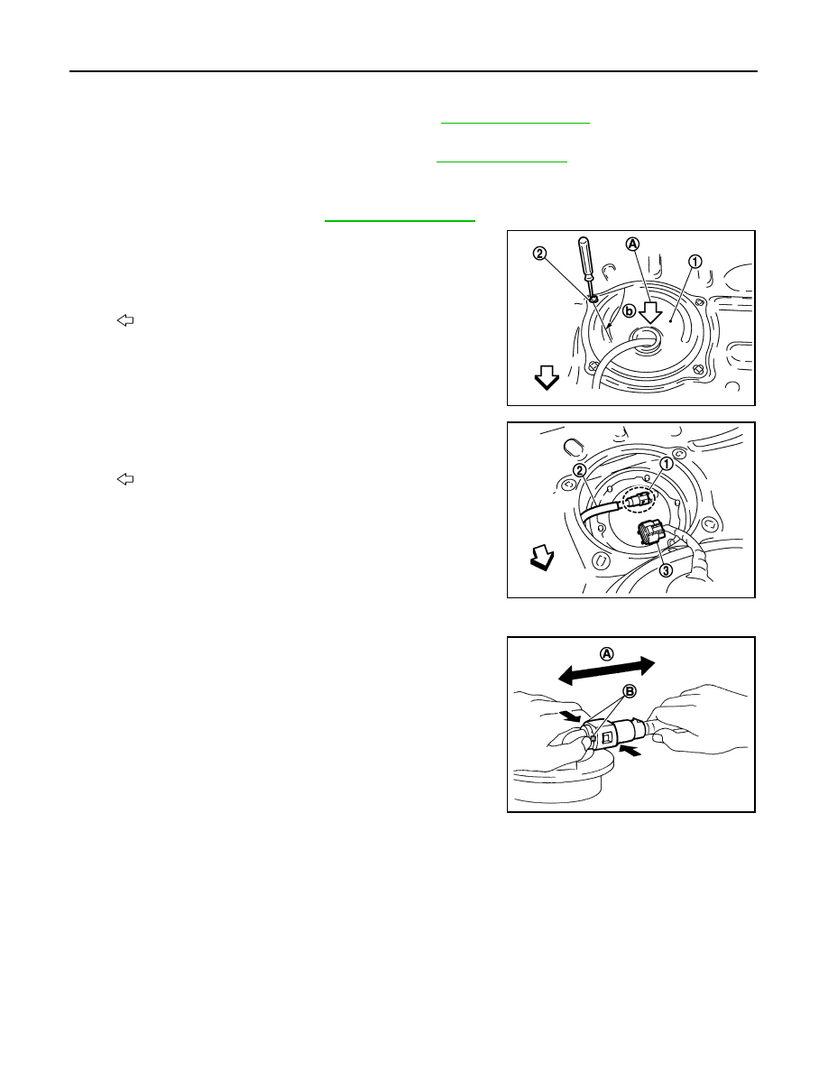
6.
Peel off floor carpet, then remove inspection hole cover (1) units
by turning clips (2) clockwise by 90 degrees.
7.
Disconnect harness connector (3) and fuel feed tube (2).
Disconnect quick connector as follows:
• Hold the sides of connector, push in tabs and pull out fuel feed
tube.
• If quick connector sticks to tube of main fuel level sensor unit,
push and pull quick connector several times until they start to
move. Then disconnect them by pulling.
CAUTION:
A
: Direction mark
b
: 90
°
: Vehicle front
Right side
: Main fuel level sensor unit, fuel filter
and fuel pump assembly
Left side
: Sub fuel level sensor unit
JPBIA0132ZZ
1
: Quick connector
: Vehicle front
JPBIA0133ZZ
A
: Pull
B
: Push in tabs
JPBIA0134ZZ